CATEGORIES:
BiologyChemistryConstructionCultureEcologyEconomyElectronicsFinanceGeographyHistoryInformaticsLawMathematicsMechanicsMedicineOtherPedagogyPhilosophyPhysicsPolicyPsychologySociologySportTourism
Hamming code
The Hamming code principle consists of using several check bits in order to refine error detection to the point where it is possible not just to detect single-bit errors but also to pinpoint their location. Once the error bit in a binary code is located, it can be corrected by complementing it.
The question of how many check bits are required for this purpose is easily answered: with k check bits, 2k different bit locations can be identified. With m data bits, the resultant total word length is m + k. An additional check bit I combination is required to indicate whether the data word received is correct.
This yields the condition
2k ³ m + k +1 .
The most important practical solutions are listed in Fig. 3.16. It can be seen I that the relative proportion of check bits is smaller the greater the word length.
We shall now examine the procedure for determining the check bits, using a 16-bit word as an example. Figure 3.16 shows that to safeguard 16 bits we need 5 check bits, i.e. a total word length of 21 bits. In accordance with Hamming, the individual check bits are evaluated as parity bits for different parts of the data word. In our example we therefore require 5 parity generators. Their inputs are allocated to data bits in such a way that each data bit is connected to at least 2 of the 5 generators. If a data bit is now read incorrectly, there is a difference only between those parity bits affected by that particular data bit. Using this method we therefore obtain a 5-bit error word, the syndrome word, instead of a parity error signal f. It can assume 32 different values which allow us to pinpoint the error bit. It can be seen that the identification of ir single-bit error is unique only if a different parity bit combination is selected for each data bit location. If a difference in just one parity bit is detected, only the parity bit itself can be in error since the parity bit combination chosen means that, for an incorrect data bit, at least two parity bits have to diner. If all the data bits and parity bits are read without error, the calculated parity bits match those stored and the syndrome word becomes F = 0.
| Number of data bits | m | 1 ...4 | 5...11 | 12 ... 26 | 27 ... 57 | 58 ... 120 | 121 ... 247 |
| Number of check bits | k |
Fig. 3.16 - Minimum number of check bits required detecting and correcting a single-bit error, relative to the length of the data word.
An example of the assignment of the five parity bits to the individual data bits is given in Fig. 3.17. This shows that data bit d0 affects parity bits p0 and p1, data bit d1 affects parity bits p0 and p2, etc. As required, each data bit affects a different combination of parity bits. To simplify the circuitry, the combinations have been distributed in such a way that each parity generator has 8 inputs.
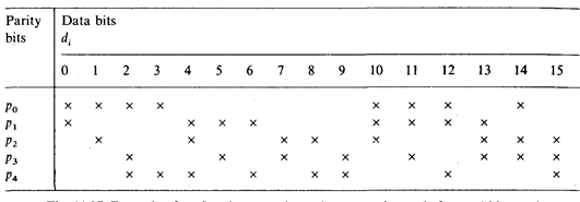
Fig. 3.17 - Example of parity bit generation using Hamming code for a 16-bit word.
During reading (R/  = 1) the syndrome generator in Fig. 3.18 compare the stored parity word P' with parity word P" calculated from data D'. If error occur, the syndrome word becomes F = P' Å P" ¹ 0. The syndrome decode then defines which data bit must be corrected and causes the bit in question to be inverted in the data corrector.
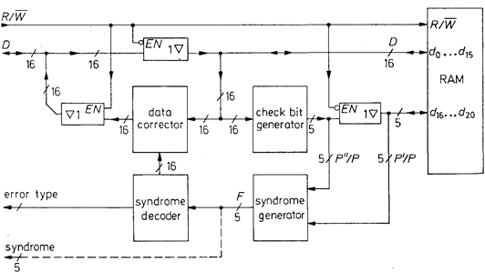
Fig. 3.18 - Data memory with error correction (using 16-bit data words as an example).
The operation of the syndrome generator will be explained more precisely with reference to Fig. 3.19. Depending on the syndrome word f0 ... f4, three types of error can be identified: Data errors d0 … d15, check bit errors p0 ... p4 and multiple errors. The latter type, however, are not completely detected when a Hamming matrix of minimum size is used, and cannot be corrected [3.8, 3.9].
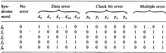
Fig. 3.19 - Table of the syndrome words and their significance.
The particular advantage of memories with error correction facilities is that the occurrence of memory errors can be registered, while remaining ineffective as a result of the correction procedure. However, in order to derive maximum benefit from this, a number of factors have to be taken into consideration: the probability of non-correctable multiple errors must be minimized. For this reason a separate memory IC should be used for each data bit d0 ... d15 and each check bit p0 ... p4. Otherwise several data bits would be simultaneously falsified in the event of total failure of a memory chip. In addition, it is necessary for each error detected to be rectified as quickly as possible. Consequently, a program is interrupted when an error is detected in the computer memory and I an error service program is executed. This must first establish whether this error is a transient error which can be rectified by writing the corrected data word back into memory and then reading it out again. If the error persists, it is a permanent error. In this case the syndrome word is read out, as this allows the memory IC involved to be located and the IC number together with the frequency of failure are listed in a table. This table can then be scanned at regular intervals so that defective chips can be replaced. This enables the reliability of a memory with EDC (Error Detection and Correction) to be continually increased.
Figure 3.20 lists some of the integrated EDC controllers available. All types use an additional check bit, which enables all double errors to be detected; however, only the single errors can be corrected [3.10].
| Word length | Type | Manufacturer | Check bits | Correction time | Power dissipation | Pins |
| 8 bit | 74LS636 | Texas Instr. | 45ns | 450 mW | ||
| 16 bit | 74LS630 | Texas Instr. | 50ns | 600 mW | ||
| 16 bit | IDT39C60 | IDT | 30ns | 300 mW | ||
| 16 bit | Am29C60 | AMD | 50ns | 250 mW | ||
| 32 bit | 74ALS632 | Texas Instr. | 60ns | 780 mW | ||
| 32 bit | IDT49C460 | IDT | 35ns | 350 mW | ||
| 32 bit | Am29C660 | AMD | 50ns | 300 mW |
Fig. 3.20 - Error correction Ics.
Date: 2015-01-12; view: 2894
| <== previous page | | | next page ==> |
| Parity bit | | | ROM with singl programming |