CATEGORIES:
BiologyChemistryConstructionCultureEcologyEconomyElectronicsFinanceGeographyHistoryInformaticsLawMathematicsMechanicsMedicineOtherPedagogyPhilosophyPhysicsPolicyPsychologySociologySportTourism
Brief theoretical information
The electric circuit of sinusoidal alternating current, containing a resistor with resistance R connected in parallel, a real inductor having a full resistance ZK, including its active resistance RK and inductive resistance XK , and a capacitor with capacitive resistance Xc shown in fig. 4. 6.
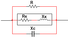
Fig. 4. 6. Circuit diagram of electric circuit with parallel connection of elements
According to the first Kirchhoff law in a complex form for currents through the elements of the circuit at flowing current can be written:
IR + IK + IC = I.
Given the fact that, as follows from the experiments conducted in section 4.1, the complex vectors of current through resistive circuit elements coincide in direction with the vectors of the voltage drop across them, the vector of the current through an ideal inductor lags by 900, and the vector of the current through the capacitor is ahead of the 900 vector of the corresponding voltage drop for modules of all these currents can be recorded:
I = 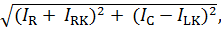
where IRK, ILK - modules of active and inductive currents through the inductor, the replacement circuit which is converted into a parallel circuit of the resistor and the ideal inductor.
By presenting the current modules in the resulting expression as products of the voltage module on the circuit and the conduction modules of the corresponding elements, we obtain the Ohm's law for the sinusoidal current circuit with a parallel connection of the elements:
I = U ∙ 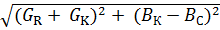 = U ∙ Y,
where BC, BK ? modules capacitive and inductive conductivity of a capacitor and a coil respectively;
Y ? the module is complete the conductivity circuit sinusoidal current.
The phase angle between voltage and total current of a parallel circuit of sinusoidal current
φ = arctg[(BK ? BC)/(GR + GK )].
If the inductor conductivity module in the circuit BK ? BC = 0, the current module in the circuit will be minimal and determined from the expression
I = U ∙ (GR + GK).
This mode of operation of the circuit is called resonance currents. With resonance the circuit conductivity has an active character, and the voltage and current vectors of the circuit will to match the phase.
Complex conductivity real inductance coil
YK = 1 / ZK=1 / (RK + ϳ ∙ XK)=RK / (RK2 + (ω ∙ LK)2) ? ϳ ∙ ω ∙ LK / (RK2 + (ω ∙ LK )2).
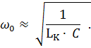
Hence condition the emergence of resonance
ω0 ∙ LK / (RK2 + (ω0 ∙ LK)2) = ω0 ∙ C.
If RK ≪ ω ∙ LK
Date: 2018-08-27; view: 28058
| <== previous page | | | next page ==> |
| Brief theoretical information | | | Procedure for conducting experiments |