CATEGORIES:
BiologyChemistryConstructionCultureEcologyEconomyElectronicsFinanceGeographyHistoryInformaticsLawMathematicsMechanicsMedicineOtherPedagogyPhilosophyPhysicsPolicyPsychologySociologySportTourism
Brief theoretical information
The electric circuit of sinusoidal varying current, containing series-connected resistor c resistor R, a real inductor with impedance Z, which includes the active resistance RK and inductive reactance XK , and a capacitor with capacitive impedance XC as shown in fig. 4. 4.
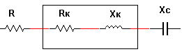
Fig. 4. 4. The scheme of the electric circuit of the sinusoidal current at the serial connection of the elements
According to the second Kirchhoff law in a complex form for voltage drops on the elements of this circuit with the voltage U applied to its outputs, it is possible to record
UR +UK + UC = U.
Taking into account the fact that, as follows from the experiments carried out in section 4.1, the complex vector of voltage drop on the resistive element of the circuit coincides in the direction with the current vector through it, the vector of voltage drop on the ideal inductance coil is ahead by 900, and the vector of voltage drop on the capacitance lags by 900 from the vector of this current, we can write :
U =  ,
,
where URK, ULK ? voltage drop modules on the active and inductive resistance of the coil.
Presenting the modules of the voltage drops in the circuit elements is the product of the module current and module resistance, we have:
U =  = I
= I 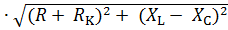 .
.
Hence the Ohm's law for a series circuit sinusoidal current:
I = U/  = U / Z,
where Z is module of the impedance of the circuit.
The angle of the swig phases between the voltage of the circuit and flowing through it current will be determined by the expression:
φ = arctg ((XK ? XC) / (R + RK).
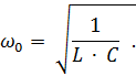
If XL = XC, the reactive resistance of the circuit X = XK ? XC = 0 and φ = 0, and the current in the circuit will be limited only by the active resistance. This type of operation of circuit is called the voltage resonance. In this case, the current in the circuit will be maximum, and the voltage on the coil and capacitor in practice increases several times. The resonance frequency of the circuit find from the equality ω0 ∙ L = 1 / (ω0 ∙ C):
Date: 2018-08-27; view: 28627
| <== previous page | | | next page ==> |
| Procedure for conducting experiments | | | Brief theoretical information |