CATEGORIES:
BiologyChemistryConstructionCultureEcologyEconomyElectronicsFinanceGeographyHistoryInformaticsLawMathematicsMechanicsMedicineOtherPedagogyPhilosophyPhysicsPolicyPsychologySociologySportTourism
DIAGRAMA FASORIAL Y CIRCUITO EQUIVALENTE DEL MOTOR POLIFASICO DE INDUCCION
Las siguientes ecuaciones son las fundamentales para establecer el Diagrama Fasorial y deducir el Circuito Equivalente del Motor Polifásico de Inducción:
V1 = -E1 + I1r1 + jI1x1
sE2’ = I2’r2’ + jsI2’x2’
E2’ = I2’r2’/s + jI2x2’
E2’ = I2’r2’ + jI2’x2’ + I2’r2’[(1-s)/s]
 I1 + I2’ = Im I1 = Im + (-I2’)
Io = If + Ih+e
E2’ = E1 = -Iozm = -(I1 + I2’)zm
Im = -E1ym = -E2’ym
zm = 1/ym
Más adelante se las utilizará para deducir las relaciones de potencia y par motor, así como también el diagrama circular.
DIAGRAMA FASORIAL.-


 I1x1 I1r1 I1 V1 -E1 -I2’ Im Ih+e If I2’r2’/s j1: Ángulo del factor de potencia E2’ = E1 I2’x2’ I2’
Tg y2s = I2’x2’ / I2’(r2’/s) = sx2’/r2’

y2s = Tg-1 (sx2’/r2’)
Rango de s nominales (0.01 - 0.05)
El ángulo j1 siempre está en atraso, y esto es originado por la corriente magnetizante y por las caídas por reactancia de dispersión. Se requiere corriente reactiva para mantener ambos flujos: el principal, lo mismo que los flujos de dispersión.
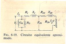
CIRCUITO EQUIVALENTE.-

 V1 = -E1 + I1r1 + jI1x1 V1 = -E1 + I1(r1 + jx1)V1 = -E1 + I1z1

 E2’ = I2’r2’/s + jI2x2’ E2’ = I2’(r2’/s + jx2’) E2’ = I2’z2’ ‚

 I1 + I2’ = Im = -E1ymIm = -E1/zm ƒ
 |

zm = Rm + jXm „Rm = Gm / (Gm2 + Bm2)
 Xm = Bm / (Gm2 + Bm2)
ym = Gm – jBm …Gm = Rm / (Rm2 + Xm2)
Bm = Xm / (Rm2 + Xm2)
 I1 + I2’ = Im = -E1ym= -E1/zm I2’ = Im – I1
E2’ = E1 = I2z2’
E1 = (Im – I1)z2’ = Imz2’ – I1z2’
E1 = -E1ymz2’ – I1z2’
E1 + E1ymz2’ = -I1z2’ E1(1+ ymz2’) = -I1z2’
E1 = -(I1z2’)/(1+ymz2’) = -I1/(1/z2’ + ym)
V1 = I1 / (1/z2’ + ym) + I1z1 = I1 [z1 + 1/(1/z2’ + ym)]

V1/I1 = zc = z1 + 1/(1/z2’ + ym)


 I1 z1 z2’ ym V1
Circuito Equivalente del Motor de Inducción
Circuito Equivalente

Circuito Equivalente Aproximado

DIFERENCIAS ENTRE CIRCUITOS REALES Y CIRCUITOS EQUIVALENTES
| CIRCUITO REAL | CIRCUITO EQUIVALENTE |
| § E2 es proporcional a “s” | § E2’ no es función de “s” |
| § X2 es proporcional a “s” | § X2’ no es función de “s” sino que es constante. |
| § E2 e I2 tienen una frecuencia f2 = sf1 | § E2’ e I2’ tienen frecuencia f1 |
| § I1 + I2 = Im | § I1 – I2’ = Im I1 + (-I2’) = Im |
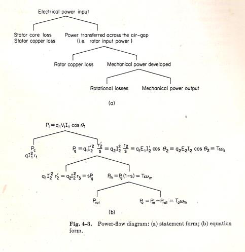
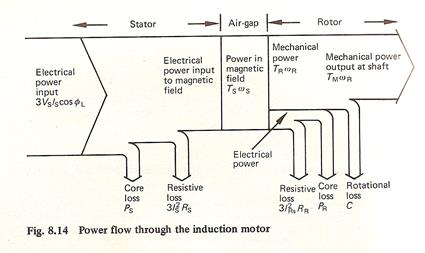
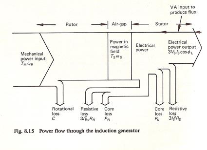
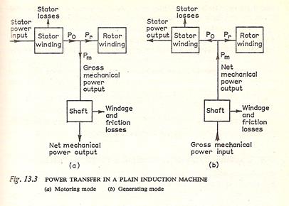
DIAGRAMA DE FLUJO DE POTENCIAS
MOTOR:


 P.Salida Potencia de Entrada Potencia Electromagnética P.eje Potencia Eléctrica P.mecánica m1V1I1Cosj1 Pferot PF+V P(h+e)2 Pcu2 = m2I22r2 P(h+e)1
Pcu1 = m1I12r1
Date: 2015-12-24; view: 966
| <== previous page | | | next page ==> |
| CUADRO COMPARATIVO ENTRE EL TRANSFORMADOR Y EL MOTOR DE INDUCCION | | | RELACIONES DE POTENCIA Y PAR MOTOR |