CATEGORIES:
BiologyChemistryConstructionCultureEcologyEconomyElectronicsFinanceGeographyHistoryInformaticsLawMathematicsMechanicsMedicineOtherPedagogyPhilosophyPhysicsPolicyPsychologySociologySportTourism
The relative information transfer rate of cyclic codes
To determine the optimal parameters of CC use the formula for the relative information transfer rate
R = C/B = k/n. (1.11)
where C – information transfer rate, (bps);
B – modulation rate, (baud).
The length of the code combinations n could be chosen to ensure maximum capacity of a discrete communication channel. Obviously, when the larger the ratio k/n approaches 1, smaller C differs from B and the relative information transfer rate is higher. It is known that for cyclic codes with minimum code distance d0 = 3 the inequality is correct:
r ≥ log2(n + 1).
Evidently, that than more n, the nearer the relation k/n is approached by 1. This inequality also is correct for large d0, although there are not exact correlations between r and n. There are only high and lower bounds estimations of minimum code distance (1.7) – (1.10). From the point of bringing of the permanent redundancy in the code combination, it is advantageous to choose long code combinations, because with the increasing of n, a relative bandwidth increases, tending to the limit = 1.
There are interferences in the real communication channels, resulting in appearance of errors in the code combinations. At detecting an error in the systems with the automatic repeat request (ARQ), a decoder produces the request of the code combinations group. During request useful information is not transmitted, information transfer rate decreases therefore. It is possible to show that

 (1.12)
where Pdet – probability of the detected errors by a decoder (probability of request);
Pcr – probability of correct reception of the code combination;
M – capacity of the transmitter buffer on the certain number of the codewords.
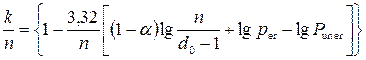
After simplifications and transformations of the formula (1.12), for the case of independent distribution of errors, get the information transfer rate
 , (1.13)
where per – error probability in the communication channel;
L – the distance between the transmitter and receiver, km;
V – the signal propagation velocity, km/sec. Usually V = 280000 km/sec.
Thus, the relative information transfer rate of the channel is
 . (1.14)
So, at presence of errors with the independent distribution in a communication channel a value R is a function of the parameters per, n, k, L and V. Consequently, there is optimal n, at that a relative information transfer rate will be maximal.
For engineering calculations wide application was found a model of the errors stream, offered by L. P. Purtov, which with sufficient accuracy for practice describes characteristics of errors stream with bursts.
Investigating statistics of errors in a communication channel, it has been noticed, that the probability of errors of multiplicity t in n-digit code combination is equal to:
 ; (1.15)
where α ‑ factor of bursts of errors in the discrete channel.
For the ideal channel without bursts (without memory) α = 0, and if α = 1 errors are concentrated in one package.
If the cyclic code is used in the mode of the errors detection by multiplicity t, then the formula (1.15) with account (1.5) will be:
 . (1.16)
With some approximation it is possible to associate the probability of errors of multiplicity t [P(  t, n)] with probability of the undetected errors Pun er and the number of check bits in a code combination as follows:
 (1.17)
Having substituted in the formula (1.17) value P( t, n) and, having executed transformations, we can calculate r
 (1.18)
In engineering calculations it is more easy to use decimal logarithms, so (1.18) became
 (1.19)
Let’s substitute k on (n-r), and (1.19) will be
 (1.20)
Finally the formula for calculating the relative information transfer rate with accounting (1.16) and (1.20):
 (1.21)
1.2.3 Basic principles of cyclic сodes encoders construction
In the beginning let’s consider the construction of the cyclic codes (n, k) encoders. At their construction, as a rule, the division of the combination of the simple k-code, multiplied by хr is used, that allows to get a separable code. The construction of encoder is shown in a fig. 1.2. It has r-digits shift register (the amount of memory cells is equal to the number of check bits), three keys and two-input adders modulo 2, thus number of them is less the number of nonzero members of generator polynomial Р(х) on one. A structure of logical feed-backs in the shift register is defined by the type of generator polynomial
P(x) = a0 + a1x+ a2x2 +…+ ar-1xr-1+ arxr.
Adders modulo 2 (m2) are present in a chart in the case, if corresponding coefficients are equal “1”.
An encoder works as follows. In the beginning the electronic key К2 is closed, and the electronic keys К1 and К3 are open. Informative sequence (code combination of the simple k-element code) enters simultaneously the input and the input of adder. In the process of its passing on the k-th clock cycle, the binary elements of r check bits accumulate in the cells of the shift register. In the (k+1)-th clock cycle the electronic keys К1 and К3 close, and the electronic key К2 opens. Written in the cells of shift register r check bits after r clock cycles enter the output of the encoder.
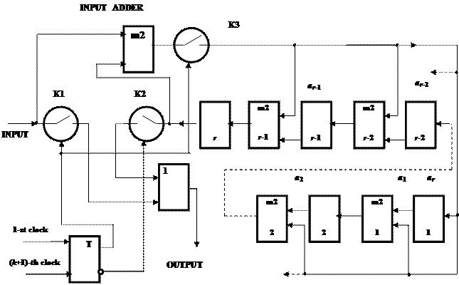
Figure 1.2 – Flow diagram of the cyclic (n, k) code encoder
Date: 2015-02-16; view: 1458
| <== previous page | | | next page ==> |
| Cyclic codes | | | Syndrome decoding of cyclic codes |