CATEGORIES:
BiologyChemistryConstructionCultureEcologyEconomyElectronicsFinanceGeographyHistoryInformaticsLawMathematicsMechanicsMedicineOtherPedagogyPhilosophyPhysicsPolicyPsychologySociologySportTourism
Flip-flops with intermediate storage
For many applications, such as counters and shift registers, transparent flip-flops are unsuitable. In these cases flip-flops are required which temporarily store the input state and only transfer it to the output when the inputs are inhibited once more. They therefore comprise two flip-flops: the master flip-flop at the input and the slave flip-flop at the output.
Two-edge-triggered flip-flop
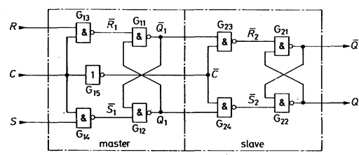
Figure 2.12 shows a master-slave flip-flop of this kind. It consists of two statically clocked RS flip-flops of the type shown in Fig. 2.7. The two flip-flops are mutually inhibited by complementary clock signals. Gate G15 is used for clock inversion. As long as clock C = 1, the input information is read into the master. The output state remains unchanged, because the slave is disabled.

Fig. 2.12 - RS master-slave flip-flop.

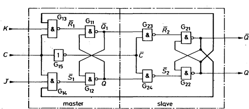
Fig. 2.13 - JK master-slave flip-flop.
When the clock goes to 0, the master is disabled, thereby freezing the state present immediately prior to the negative-going edge of the clock signal. The slave is simultaneously triggered, thus transferring the state of the master to the output. Data transmission therefore occurs on the negative-going edge; how-ever, there is no clock state in which the input data have a direct effect on the output, as is the case with transparent flip-flops.
The input combination R = S = 1 necessarily results in an undefined behavior, because inputs  ,
,  in the master simultaneously go from 00 to 11 when clock C goes to 0. In order to be able to make use of this input combination, the complementary output data are additionally applied to the input gates. The feedback circuit shown in heavy type in Fig. 10.11 is used for this purpose. The external inputs are then designated J and K respectively. We can see from the truth table in Fig. 10.12 that the output state for J = K = 1 is inverted at each clock pulse. This is the same as dividing the frequency by two, as Fig. 2.13 shows. Consequently, JK master-slave flip-flops provide a particularly simple means of constructing counters.

Fig. 2.14 - Output state of a JK master-slave Fig. 2.15 - JK master-slave flip-flop as flip-flop after a (010) clock cycle. frequency divider (J = K = 1).
However, because of the feedback, operation of the JK flip-flop is subject to an important limitation: the truth table in Fig. 2.14 only applies if the state at the JK inputs remains unchanged as long as clock C is 1. This is because, unlike the RS master-slave flip-flop in Fig. 212, the master-slave flip-flop here ca only change state once and cannot change back, as one of the two input NAND gates is always disabled by the feedback. Failure to observe this limitation a frequent source of errors in digital circuits.
Special types of JK master-slave flip-flops are available which are not subject to this limitation. They are provided with data lockout: the input state read in is precisely the one present on the positive-going edge. Immediately after this edge, the two input gates are disabled and no longer react to changes. This is made clear in Fig. 2.16. Whereas with normal JK flip-flops the J and K inputs must not change as long as clock C = 1, with a data lockout JK flip-flop they must remain constant only during the positive-going edge of the clock signal. The common feature of both flip-flops is that the information read in on the positive-going edge of the clock signal does not appear at the output until the negative-going edge. Due to this delay, the circuit symbol in Fig. 2.17 additionally has a delay sign at the outputs.

Fig. 2.16 - Timing diagram of the input and output Fig. 2.17 - Circuit symbol of a JK signals of JK master-slave flip-flops. master-slave flip-flop.
JK flip-flops frequently have several J and K inputs leading to an internal AND gate. The internal J and K variables are then only 1 when all the respective J and K inputs are 1.
In addition to the JK inputs, the JK flip-flops additionally possess Set and Reset inputs which operate independently of the Clock - i.e. asynchronously. This enables master and slave flip-flops to be set or cleared. The RS inputs have priority over the JK inputs. In order to allow clock-controlled operation, either R = S = 0 or  = 1.
= 1.
Typical IC types:
TTL ECL CMOS
Standard 7476 10135 4027
Data lockout 74LS111
Date: 2015-01-12; view: 1914
| <== previous page | | | next page ==> |
| Clocked RS flip-flop | | | Flips types |