CATEGORIES:
BiologyChemistryConstructionCultureEcologyEconomyElectronicsFinanceGeographyHistoryInformaticsLawMathematicsMechanicsMedicineOtherPedagogyPhilosophyPhysicsPolicyPsychologySociologySportTourism
Shifter Networks
We consider next how large shifters can be realized using the k-bit p-shifter modules described. We consider only the case of unidirectional right-shift. In what follows we assume that all shifters and shifter modules are of this unidirectional type, without explicitly saying it each time. The modifications for left and for bidirectional shift are left for Exercise 4.40.
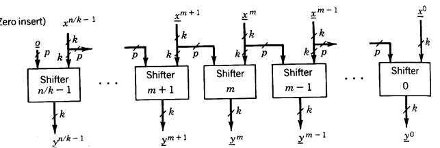
An n-bit p-shifter can be implemented with n/k k-bit p-shifter modules as illustrated in Figure 1.57. The p least significant inputs of the (m+1)st module are the same as the p most significant inputs of the mth module. The delay of this shifter is the same as the delay of a shifter module.

Fig. 1.57 - Right p-shifter network (Sift control not shown).
A 12-bit 3-shifter, implemented by three 4-bit 3-shifter modules, is illustrated in n The mode of operation is shift right 0, 1, 2, or 3 places with 0 insert.

Fig. 1.58 - A 12-bit right 3-shifter.
An n-bit q-shifter can be implemented in several ways using k-bit p-shifter modules (n > k, q >p). One such implementation is described in the following example.
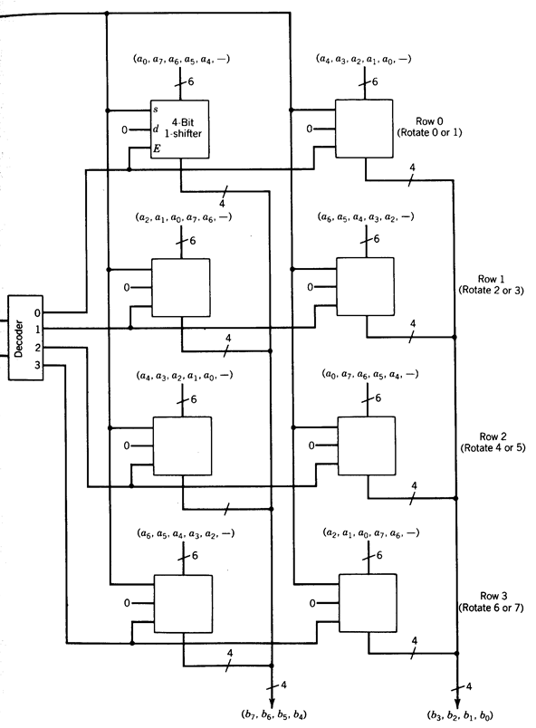
Figure 1.59 shows the implementation of an 8-bit 7-shifter using 4-bit l-shifter modules and a 2-input binary decoder. The input is a = (a7 , . . . , a0), the output is b = (b7, … , b0), and the operation mode is Rotate Right 0, 1, . . . , 7 position.
The shifter network is organized as a rectangular array of shifter modules. Each row corresponds to an 8-bit 1-shifter. The first row can rotate 0 or 1 positions, the second row can rotate 2 or 3 positions, and so on, the last row rotating 6 or 7 positions. The decoder enables one of the rows, and the outputs of the rows use a wired-OR connection.

Fig. 1.59 - Array implementation of an 8-bit 8-shifter (right rotate only).
Date: 2015-01-12; view: 1599
| <== previous page | | | next page ==> |
| Conversion of BCD to straight binary code | | | Comparators |