CATEGORIES:
BiologyChemistryConstructionCultureEcologyEconomyElectronicsFinanceGeographyHistoryInformaticsLawMathematicsMechanicsMedicineOtherPedagogyPhilosophyPhysicsPolicyPsychologySociologySportTourism
Brief information from the theory
The three-phase system was first created to solve the problem of converting electrical energy into mechanical energy by creating a circular rotating magnetic field. It is widespread due to the simplicity of the three-phase asynchronous motor.
The main elements of three-phase circuits are three-phase generator, three-phase transformer, single-phase or three-phase load and connecting wires.
A three-phase generating system can be created from three single-phase sources, the EMF of which can be represented by expressions:
eA = EAm ∙ sin ω ∙ t;
eB = EBm ∙ sin (ω ∙ t + 2400);
eC = ECm ∙ sin (ω ∙ t + 1200).
In complex form these EDS can be recorded:
EA = EAm ∙ e j∙ω t;
EB = EBm ∙ e(ϳ∙ω∙t-120˚) ;
EC = ECm ∙ e(ϳ∙ω∙t-240 ˚).
The time diagram of the three-phase voltage generator is shown in fig. 5.1.
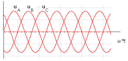
Fig. 5.1. The timing diagram of voltages of three-phase generator
Most often, the energy systems of industrial, administrative and residential complexes will be implemented according to the star-star scheme with a zero wire, as shown in fig. 5. 2 a, sometimes under the scheme "star" - "star" shown in fig. 5..2 b.
There are the following types of three-phase loads.
1. A symmetrical load, which is equal to the complex impedance voltages phase of the receiver:
ZA = ZB = ZC = ZA ∙  .
.
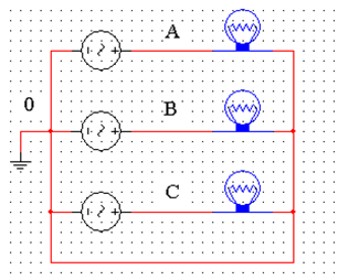
a
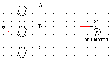
b
Fig. 5. 2. Connection scheme of three-phase systems: a ? ?star? - ?star? with zero wire, b ? ?star? - ?star?
1. Uniform load at which the resistance modules of the receiver phases are equal:
ZA = ZB = ZC.
2. Uniform load, which is equal to the arguments of the resistance and the phase of the receiver:
ⱷA = ⱷB = ⱷC.
3, Asymmetric load at which resistance complexes are not equal in all phases of the receiver:
ZA ≠ ZB ≠ ZC.
For the ?star? - ?star? scheme with zero wire under arbitrary load, the following relations are valid for the phase current complexes
Ia = Ua / Za ; Ib = Ub / Zb ; Ic = Uc / Zc.
For neutral current (zero wire):
I0 = Ia + Ib + Ic .
For linear and phase voltages of the same circuit
Ul =  ∙ Uph.
At symmetric load, the phase current modules are equal to each other
Ia = Ib = Ic = Uph / Zph,
and the current in the neutral is zero
I0 = 0.
For the "star" - "star" schema without neutral for arbitrary load neutral voltage
UN = (UA * Ya+ UB ∙ Yb + UC∙ YC) / (Y0 + Ya + Yb + Yc).
The voltage on the load phases,,
U?a = UA̶ UN ; U?b = UB̶ UN ; U?c = UC̶ UN.
The currents in the phases of the load:
Ia = U?a / Z? ; Ib= U?b/ Zb ; Ic= U?c/ Zc..
At the same time, in each phase of the circuit, a complex linear currents is equal to the phases current.
Il = Iph .
Phase shift angles between phase currents and voltages
ⱷa = arctg (Xa / Ra); ⱷb = arctg (Xb / Rb); ⱷc = arctg (Xc / Rc),
where Ra, Rb, Rc ? resistance of the load phases;
Xa, Xb, Xc ? their reaction resistances.
Active power of three-phase circuit under arbitrary load
P = Pa + Pb + Pc ;
reactive power
Q = Qa + Qb + Qc ;
full power
S =  .
.
With a symmetrical load
P = 3 ∙ Uph ∙ Iph ∙ cos ⱷl =  ∙ Ul ∙ Il ∙ cos ⱷl;
Q = 3 ∙ Uph ∙ Iph ∙ sin ⱷl = ∙ Ul ∙ Il ∙ sin ⱷl;
S = 3 ∙ Uph ∙ Iph = ∙ Ul ∙ Il .
Date: 2018-08-27; view: 28195
| <== previous page | | | next page ==> |
| Procedure for conducting experiments | | | Procedure for conducting experiments |