CATEGORIES:
BiologyChemistryConstructionCultureEcologyEconomyElectronicsFinanceGeographyHistoryInformaticsLawMathematicsMechanicsMedicineOtherPedagogyPhilosophyPhysicsPolicyPsychologySociologySportTourism
The capabilities of the software environment Multisim 10.1.1
If you have installed the program Multisim, run execute it through the Start menu of the Windows program. Running the program can be carried out, for example, according to the scheme: Start / All programs / National Instruments / ?ircuit Design Suite 10.1 / Multisim 10.1.1.
In the process of starting a program first displays a window with its name,
and then the main window (fig. 1.1).
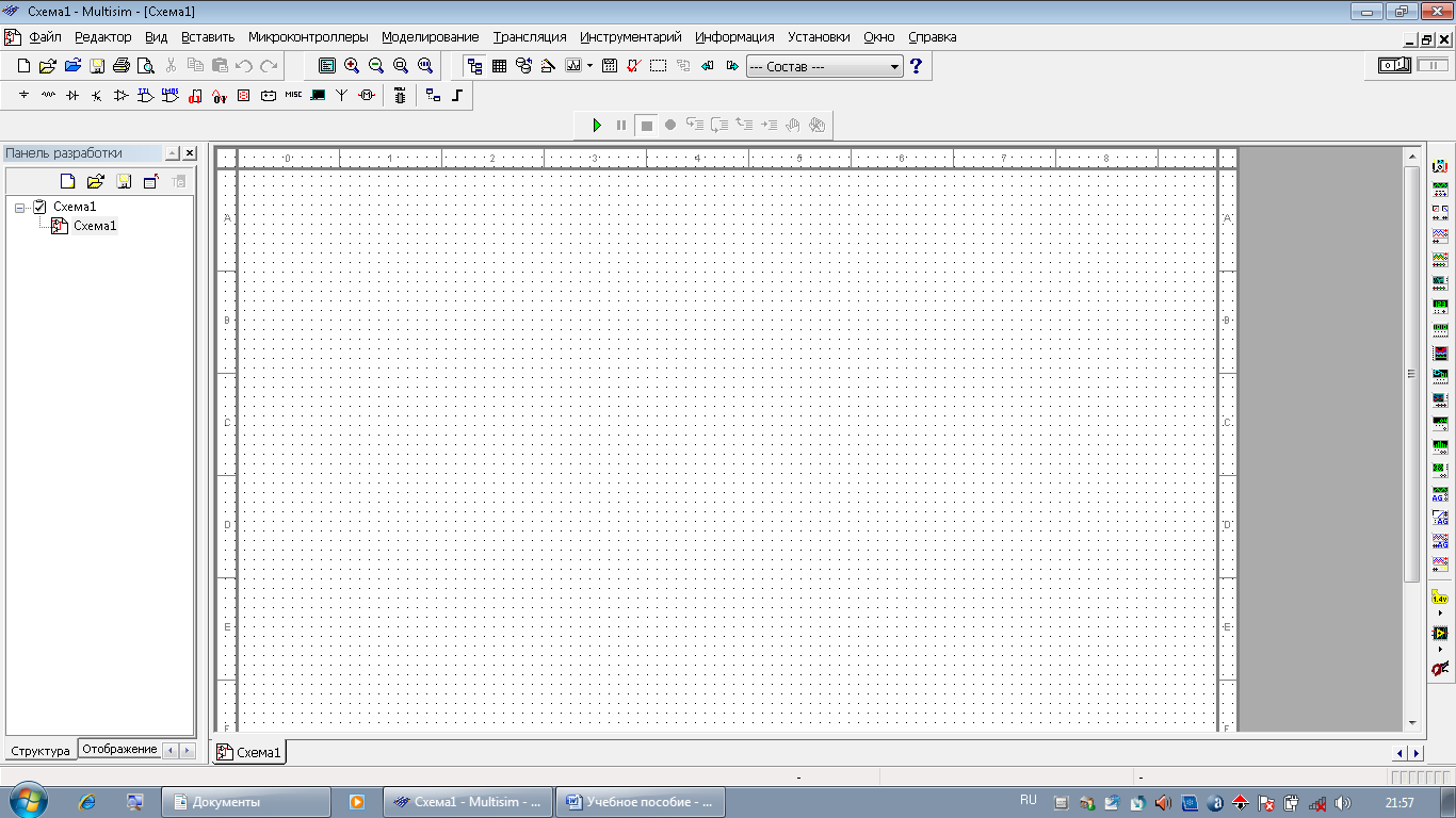
Fig. 1.1. The main window of Multisim 10.1.1
The opened window contains Main menu, Toolbar, Status bar, scroll bars and other window elements to your Windows environment.
Main menu items: File, Editor, View are regular sets of commands to work with files and projects, print (File), edit and change the properties of the circuit layout, orientation, deleting, allocation, moving of model elements (Editor), settings of user interface with the ability to modify dashboards and zooming the workspace (View). The menu item to Insert is intended for selection and placing of circuit components, cables, tires and definitions electrical components-connectors, as well as to determine the review, the introduction of connectors and explanatory text, insert basic graphic elements, graphic images from external files, etc. Item in this menu, the MCU determines the capabilities of the programming of microprocessors and analyzing decisions made. The menu item Simulation determines the types of analysis being undertaken, it is also possible to choose built-in appliances, save the simulation results and hold processing. The menu item allows the Stream to pass initial data to trace printed circuit boards to additional programs Ultiboard 9 or 10 version. The menu Toolkit is the opportunity to work with the database components of the environment, to use computer-aided design, potential design, etc. In this menu it is possible to determine the source of data for multivariate analysis, the verification of the developed scheme on the error, the edit symbols of electronic components, the definition of the capture area on the graph and the fragment of the graphic image file. The item Information menu allows you to get a report on the developed scheme, for example, on the number and types of circuit components, their parameters, etc.
The menu Setup is designed to set the conditions of work programme for the preparation for storing the circuit file to define the appearance of the scheme and the conditions of entry and placement of elements. For example, this paragraph defines the modes and conditions of operation of the program, as in the process of entering the schema and maintain the schema in a file, the path to the folder storage schema files, configuration files, and databases, modes of preservation and the size of the data file. Here you can define the program in the selection and installation of components to the workspace schema, the choice of the standard component tags, the parameters of the automated measurement of experimental results, the simulation parameters of digital devices and the effect of the program during automatic connection of conductors and choice is allocated to the movement of the cursor regions. In addition, in this menu item you can specify which information will be displayed on the desktop scheme next to the entered component. Often, redundant information about a component can make it difficult to read. In this regard, it is possible to recommend to use to display only the necessary information, e.g. text labels, component names, values values of their basic parameters, the labels of nodes and their numbering. The item window allows you to define the color of the components on the working area, the color of the connecting wires or you can specify a color palette. To use the specified settings in the development and other schemes you must check their conservation. This menu item allows you to select or deselect the visibility of the grid working area to set the boundaries of drawing and visualization, to define the page size for diagrams of standard kits, its orientation or to define custom page sizes, define the line thickness of the connecting wires and the thickness of the image bus scheme.
The Main menu item Window makes a transition from one inner window to another and regulates the location of these Windows. Using the menu item help you can obtain information about the program being used.
Service panel of the program Multisim 10.1.1 appear at the command of the View menu when they are selected. These include Panel design, Panel schematic, Panel control modeling of microprocessors and the Panel editor. The last panel appears when you enter the command View / Toolbar / Panel editor.
The Panel design allows control of operation of the program, to open and close the schema files. It is located to the left of the main window has the following tabs: create a new file, open file, save changes to close the schema file, rename the file.
Control panel simulation of microprocessors located in the center of the main window directly above the main program window.
Panel schematic located under a service Panel design and has tabs: Structure, Display, View project. On the Structure tab you can see the schema files that are open in the program. You can rename them, close, or save. The Display tab allows you to define the visibility of schema attributes and the visibility of proprietary information.
The Panel editor located above the main program window left and right of the Panel control modeling microprocessors and allow for quick editing, and search components, including the values given to their parameters.
In addition to these panels, on the top right above the main window of the program located in the switch process simulation and the switch pauses in the simulation schemes.
Date: 2018-08-27; view: 28777
| <== previous page | | | next page ==> |
| ELECTRICAL ENGINEERING IN EXPERIMENTS | | | Components of the program Multisim |