CATEGORIES:
BiologyChemistryConstructionCultureEcologyEconomyElectronicsFinanceGeographyHistoryInformaticsLawMathematicsMechanicsMedicineOtherPedagogyPhilosophyPhysicsPolicyPsychologySociologySportTourism
Specification table of the equipment and devices
SPECIFICATION TABLE
| No. | Name | Mark | Parameter | Symbol | Amount |
| Air compressor | Compressor. Power plus. Silent operation. Model: POW547 Serial number: 2003-2717-001412 | 230V, 50Hz Max. pressure: 7.0bar/100Psi | - | ||
| Knob | Knob | Max. pressure 100 Psi | - | ||
| Service Unit | Regulator. Camozzi. N208-D00. | In. P. max. 16bar. Out P. 0.5-10bar. T. max. 60 C | - | ||
| E/P converter | Transducer. ControlAirInc. AmherST, NH. Type 500x. I/P transducer | Input: 4-20mA. Output: 3-15Psi. Supply: 18-100Psi | |||
| Regulator 1 | Regulator. Camozzi. M008-R00 | In. P. max. 16bar. Out P. 0.5-10bar. T. max. 60 | - | ||
| Flow Meter | Flow Meter | Range: 0-1000 | - | ||
| Control Valve | Jordan Valve, OH. 45209. Model: 708. Serial: 1035548A | Size: ¼. Range: 3-15Psi. Max. T. 500 F | - | ||
| Tank | Assouline Compressors ltd, 77 | - | |||
| SW | Switch | - | - | ||
| G1,G2 | Gauge | Range: 0-10bar | |||
| G3,G4,G5,G6,G8 | Gauge. Fimet | Range: 0-1bar | |||
| G7 | Gauge. R&R | 0-4bar | |||
| SV1, SV2 | Safety Valve | - | |||
| T1,T2,T3 | Tee | - | |||
| Tr1,Tr2 | Pressure transducer. AMT-001. MPX5100DP | ||||
| CV1,CV2 | Valve. Camozzi. RFU483 | P. max. 10bar |
Equipment
1. Air Compressor
The air compressor, as its name suggests, compresses air to a desired pressure, and supplies it to the ProcessLine Panel through a hose. The compressor can compress air to a pressure of 12 bars (180 Psi). However, the standard for the pressure control instrumentation is between 3-15 Psi (between 0.2-1bar). The air continues to flow through the panel’s components and hoses, on its way to the air tank. In our case is used POW547 model, which has the following characteristics 230V, 50Hz, 5500 rpm.

2. Tank
The air tank is the output device. Air enters the tank through an intake valve and then flows out through a variable valve (R2). As more air enters tank, the pressure increases, but this increase is tempered by the amount air exiting the system through the R2 valve. The overall goal of experiments to control the pressure in the tank by regulating various components of Pressure Control panel and R2 valve. The overall goal of the experiment is to control the pressure in the tank by regulating various components of Pressure Control panel and R2 valve.

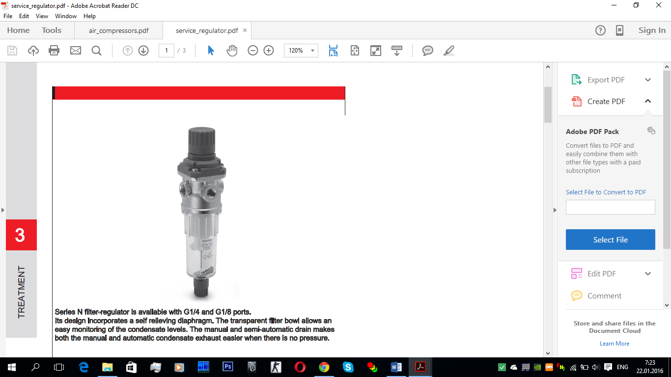
3. Service unit regulator
The service unit regulator is the device that receives air from the compressor and regulates the air that will flow through the panel. Then the air flows into two different directions. Part of air flow upwards towards E/P Converter and the Pressure Control Valve. The remainder of the air flows into Regulator 1, then into Flow Meter, the Valve seat bottom of the PCV and on into the valve R1.
Specification: Model: N208-D00, P max=16 bar, P out=5-10 bar, T max=60 C. This in effect divides the system in two. The upper half of the system, which includes E/P device and the PCV, acts to regulate the airflow through the lower half of the system.
To adjust the Service Unit Regulator:
Make sure that the Service Unit Regulator’s shut-off valve is open (pushed all the way down). The regulator’s shut-off valve at the top left of the component.
To adjust pressure, lift the knob of the Service Unit Regulator up until in snaps up, then turn the knob clockwise to increase the pressure or counterclockwise to decrease the pressure.
When the pressure is set to 30 Psi, snap the knob back down into its original position.
4. E/P Converter
The E/P Converter is constructed of the following components:
1. Fixed magnet (located on the top)
2. Electro-magnetic coil
The coil connected to an electrical signal input terminal. The coil fitted on a flexible membrane, which sits above the nozzle.
3. A diaphragm connected to the valve plug.
During the E/P operation, there is a continuous flow of air from the E/P inlet to the chamber housing the diaphragm. The rate of flow is very low and hardly noticeable. The E/P receives an electrical voltage signal from the controller. This current passed through the electro-magnetic coil. As current flows through the coil, a magnetic field is produced. This field is in opposition to the field of the fixed magnet, the result being that the coil and membrane are repelled downwards towards the nozzle.
When the voltage supplied to the coil increases:
The intensity of the magnetic field around the coil increases;
The force pushing the membrane down increases;
The membrane moves down close to the nozzle;
The flow of air through the nozzle decreases;
The pressure above the diaphragm increases;
The diaphragm is pushed down allowing freer air passage from the E/P inlet to the E/P outlet.
It is important to note that the only variable device that the controller can regulate is the E/P converter. By regulating the voltage signal sent to the E/P converter, the controller affects the characteristics of the entire system.


5. Manometer
A manometer could also refer to a pressure measuring instrument, usually limited to measuring pressures near to atmospheric. The term manometer is often used to refer specifically to liquid column hydrostatic instruments. The typical pressure sensor uses a diaphragm to convert pressure to a force, which moves the diaphragm against restoring force such as a spring, bellows or even electrically controlled force balance. The movement or the balancing force is measured as strain or displacement. The strain or displacement signal is proportional to pressure, and additional signal processing converts the signal to an electrical equivalent of pressure units that are transmitted by the analogue output. Usually the diaphragm has a reference pressure on one side, so it actually measures the difference in pressure. This can be the atmosphere for gauge sensors, a vacuum for absolute sensors, or a second pressure port for differential sensors.


6. Flowmeter
Flowmeters are used in fluid systems to indicate the rate of flow of the fluid. They can also control the rate of flow if they equipped with a flow control valve.
Flow measurement is the quantification of bulk fluid movement. Flow can be measured in a variety of ways. Positive-displacement flow meters accumulate a fixed volume of fluid and then count the number of times the volume is filled to measure flow. Other flow measurement methods rely on forces produced by the flowing stream as it overcomes a known constriction, to indirectly calculate flow. Flow may be measured by measuring the velocity of fluid over a known area.
Flowmeters consist of a primary device, transducer and transmitter. The transducer senses the fluid that passes through the primary device. The transmitter produces a usable flow signal from the raw transducer signal. These components are often combined, so the actual flowmeter may be one or more physical devices.

7. Transducers
A pressure transducer is a pressure sensor with signal processing circuit so the pressure is transmitted as an electrical analogue of the pressure. Zero pressure would be 4mA, and full scale would be 20mA. Loop up 4-20mA current loop for more info. Some may have other outputs such as serial data digital outputs, while others could have an analogue voltage, perhaps 0-10V.
A pressure transducer, sometimes called a pressure transmitter, is a transducer that converts pressure into an analog electrical signal. Although there are various types of pressure transducers, one of the most common is the strain-gage base transducer. The conversion of pressure into an electrical signal is achieved by the physical deformation of strain gages which are bonded into the diaphragm of the pressure transducer produces a deflection of the diaphragm which introduces strain to the gages. The strain will produce an electrical resistance change proportional to the pressure.


8. Regulator 1
Regulator 1 regulates a the pressure that comes from the service unit regulator and goes to flowmeter.
A pressure regulator 1 is a valve that automatically cuts off the flow of a gas at certain pressure. Regulator 1 is used to allow high-pressure gas supply lines or tanks to be reduced to safe and/or usable pressures for various application. A pressure regulator’s primary function is to match the flow of gas through the regulator to the demand for gas placed upon the system. If the load flow decreases, then the regulator flow must decrease also. If the load flow increases, then the regulator flow must increase in order to keep the controlled pressure from decreasing due to a shortage of gas in the pressure system.
A pressure regulator includes a restricting element, a loading element and a measuring element:
The restricting element is a type of valve. It can be a globe valve, butterfly valve, poppet valve or any other type of valve that is capable of operating as a variable restriction to the flow.
The loading element applies the needed force to the restricting element. It can be any number of things such as weight, a spring, a piston actuator, or more commonly the diaphragm actuator in combination with a spring.
When the actuator is forced against an expansion disk, the force is distributed among the pressure walls. This allows the gas to flow at the proper rate and not to be continually vaporized and diluted.
The measuring element determines when the inlet flow is equal to the outlet flow. The diaphragm is often used as a measuring element because it can also serve a combine element.

9. Pressure Control Valve
The large red valve that is fitted on your Pressure trainer is astandard pressure control valve, or PCV. The PCV acts to controls the flow of air in the lower half of the panel.
The pressure control valve system is composed of two subsystems: the actuator (the upper part) and the valve plug and seat (at the bottom).
The pressure supplied by the E/P acts on the actuator diaphragm. When the E/P output pressure increases, the actuator diaphragm is pushed upwards, compressing an attached spring. When the E/P pressure decreases, the spring re-compresses, pulling the diaphragm back downwards.
The diaphragm in turn is connected to the linking rod. S the diaphragm moves up or down so does the linking rod, which, in turn, moves up or down s. The air coming from Regulator 1 and the flowmeter passes between the valve seat and plug of the PCV. When the PCV moves the Valve plug down, it effectively narrows the passage across the valve seat. This increases resistance and causes a larger pressure drop. By raising and lowering the valve plug, the PCV controls the flow going to the R1 valve.


Illustration and Part list

10. R1 and R2 valves
R1 Valve is such a valve which controls the rate of air that comes as input pressure.
R2 Valve oppositely regulates the rate of air that goes as output.
The R1 and R2 valves are devices that regulate, direct or control the flow of gas by opening, closing or partially obstructing various passage ways. Valves are technically pipe fittings, but usually discussed as a separate category. In open valve gas flows in a direction from higher pressure to lower pressure.
R1 and R2 valves always use the Close position as their reference. The valve must be closed by turning the knob clockwise until it no longer turns easily. This is the Closed position. Opening of the valve is performed by turning the knob counter-clockwise to needed amount of rotations.


Date: 2016-03-03; view: 1674
| <== previous page | | | next page ==> |
| The functional scheme of Pressure Control | | | Realization of PID algorithm |