CATEGORIES:
BiologyChemistryConstructionCultureEcologyEconomyElectronicsFinanceGeographyHistoryInformaticsLawMathematicsMechanicsMedicineOtherPedagogyPhilosophyPhysicsPolicyPsychologySociologySportTourism
Non-scheduled maintenance

1 Among other things, poor engine performance may be caused by leaking valves, incorrect valve clearances, a leaking head gasket, or worn pistons, rings and/or cylinder walls. A cylinder compression check will help pinpoint these conditions and can also indicate the presence of excessive carbon deposits in the combustion chambers.
2 The only tools required are a compression gauge, with a threaded adapter to fit the spark plug hole, and a spark plug wrench. Depending on the outcome of the initial test, a squirt-type oil can may also be needed.
3 For anything more than an initial check, make sure the valve clearances are correctly set (see Section 26) and that the cylinder head bolts are tightened to the correct torque setting (see Chapter 2).
4 Refer to Fault Finding Equipment in the Reference section for details of the compression test.

1 The oil pressure warning light should come on when the ignition (main) switch is turned ON - this serves as a check that the warning light bulb is sound. If the oil pressure warning light does not come on when the ignition is turned on, check the bulb, the fuse for the tail/signal/brake/horn circuit and the oil pressure switch (see Chapter 9). The light should extinguish a few seconds after the engine is started.
2 If the oil pressure warning light fails to extinguish, or comes on whilst the engine is running, low oil pressure is indicated - stop
the engine immediately and carry out an oil level check (see Daily (pre-ride) checks). If the level is correct, test the oil pressure switch (see Chapter 9). If the switch is good, carry out an oil pressure check.
3 To check the oil pressure, a suitable pressure gauge (which screws into the crankcase) will be needed. Honda provide a gauge (Pt. No. 07506-3000000) and gauge adapter (Pt. No. 07510-4220100) for this purpose.
4 Warm the engine up to normal operating temperature then stop it.
5 Remove the oil pressure switch (see Chapter 9) and quickly screw the adapter into the crankcase threads. Connect the pressure gauge to the adapter.
| A |
Warning: Take great care not to bum your hand on the hot engine unit, exhaust pipe or with engine oil when accessing the switch take-off point on the crankcase. Do not allow exhaust gases to build up in the work area; either perform the check outside or use an exhaust gas extraction system.
6 Start the engine and increase the engine speed to 2000 rpm whilst watching the pressure gauge reading. The oil pressure should be similar to that given in the Specifications at the start of this Chapter.
7 If the pressure Is significantly lower than the standard, either the pressure regulator is stuck open, the oil pump is faulty, the oil strainer or filter is blocked, or there is other engine damage. Begin diagnosis by checking the oil filter, strainer and regulator, then the oil pump (see Chapter 2). If those items check out okay, chances are the engine bearing oil clearances are excessive and the engine needs to be overhauled.
8 If the pressure is too high, either an oil passage is clogged, the regulator is stuck closed or the wrong grade of oil is being used.
9 Stop the engine and unscrew the gauge and adapter from the crankcase.
10 Install the oil pressure switch (see Chapter 9). Check the oil level (see Daily (pre-ride) checks).
| I |
34 Steering head bearings-
lubrication
1 Over a period of time the grease in the bearings will harden or may be washed out by incorrect use of jet washes resulting in rapid wear of the bearing surfaces.
2 Disassemble the steering head for re-greasing of the bearings. Refer to Chapter 6 for details.
35 Swingarm bearings-lubrication
1 Over a period of time the grease will harden or dirt will penetrate the bearings due to failed dust seals resulting in rapid wear of the bearing surfaces.
2 Remove the swingarm as described in Chapter 6 for greasing of the bearings.
36 Rear brake cam (R and T models)- lubrication
1 Refer to Chapter 7, and remove the brake shoes and brake cam from the brake backplate as an assembly. If all components are in serviceable condition there is no need to separate the brake shoes. Clean all traces of old grease from the cam spindle and the pivot hole in the brake backplate, and the brake shoe pivot posts.
2 Apply a smear of copper-based grease to the cam spindle and the pivot posts, and to the spring hooks where they engage the holes
1.24 Non-scheduled maintenance
in the brake shoes. Install the assembly in the backplate (see Chapter 7).
3 Using the brake arm as a lever, turn the brake cam and clean all traces of old grease from both sides of the cam, then apply a fresh smear of copper-based grease to the two bearing surfaces.
4 Assemble the brake cam and shoes on the brakeplate, install the backplate in the brake drum and install the rear wheel (see Chapter 7).
Caution: Do not apply too much grease otherwise there is a risk of it contaminating the brake drum and shoe linings.
37 Exhaust system - check §$>
I
1 Periodically check the exhaust system mounting bolts for tightness. Check the cylinder head joints and silencer union for leaks. If tightening the exhaust flange nuts or silencer clamp fails to stop any leaks, renew the gaskets (see Chapter 4).
2 Clean the system and check for corrosion. Rub down any rust spots and treat with a suitable heat resistant paint. The exhaust pipe flange nuts are especially prone to corrosion. Clean the nuts and studs regularly and apply a smear of copper based grease to their threads.
38 Front forks - oil change
I
1 Fork oil degrades over a period of time and loses its damping qualities. R models are equipped with drain screws in the fork sliders and therefore changing the fork oil is a
relatively straightforward task. With all other models the fork legs have to be removed for draining and refilling.
R models
2 Support the motorcycle on its centre stand and place a support under the engine sump to take the weight off the front wheel.
3 Slacken the top yoke clamp bolts (see illustration 19.13), then remove the fork top bolts, spacers, spring seats and springs (see illustration 7.1 in Chapter 6). Use rag to prevent fork oil spillage.
| A |
Warning: The fork spring is pressing on the fork top bolt with considerable pressure. Unscrew the bolt very carefully, keeping a downward pressure on it and release it slowly as it is likely to spring clear. It is advisable to wear some form of eye and face protection when carrying out this operation.
4 Remove the drain screw from each fork
slider in turn and allow the oil to drain into a
suitable container (see illustration).
| A |
Warning: Do not allow the fork oil to contact the brake disc, pads or tyre. If it does, clean the disc with brake system cleaner, wipe off the tyre and renew the pads before riding the motorcycle. Make up a cardboard chute to direct oil away from the disc and tyre.
5 Remove the support from under the engine and allow the forks to compress slowly. Gently pump the forks to expel all of the oil then refit the drain screws with new sealing washers.
6 Slowly pour the correct quantity of the specified grade of fork oil into each leg and pump the forks gently at least ten times to distribute the oil evenly. Fully compress the fork tubes into the sliders and measure the
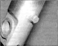
38.4 Fork oil drain screw on R models
fork oil level from the top of the tubes; if necessary, adjust the oil level by adding or subtracting oil until it is at the level specified at the beginning of Chapter 6.
7 Replace the support under the engine and fully extend the sliders on the fork tubes. Wipe any surplus oil off the springs and spacers, then install the springs with the widely spaced coils at the bottom, spring seats and spacers. Refer to Chapter 6, Section 7 for order of assembly.
8 Fit new O-rings on the fork top bolts and lubricate the rings with fork oil before installing the top bolts. Tighten the top yoke clamp bolts to the torque setting specified at the beginning of this Chapter.
All other models
9 Remove the forks from the motorcycle as
described in Chapter 6, Section 6.
10 Follow Steps 3 to 6 of Chapter 6, Section 7 to drain the fork oil, then Step 25 onwards to refill with fresh oil.
11 Refer to the Specifications at the beginning of Chapter 6 for fork oil type, quantity and level.
2»1
Chapter 2
Engine, clutch and transmission
Contents
Alternator - removal and installation ........................ see Chapter 9
Balancer shaft and bearings......................................................... 26
Camchain and guides................................................................... 27
Camchain tensioner........................................................................ 8
Camshafts - removal, inspection and installation..................... 9
Clutch cable - replacement........................................................... 14
Clutch - check.............................................................. see Chapter 1
Clutch - removal, inspection and installation .......................... 15
Connecting rods and bearings - removal, inspection
and installation............................................................................. 22
Crankcase halves and cylinder bores - inspection and servicing ... 31
Crankcase halves - separation and reassembly........................ 20
Crankshaft and main bearings - removal, inspection
and installation.......................................................................... 25
Cylinder head - removal and installation................................... 10
Cylinder head and valves - disassembly, inspection
and reassembly.......................................................................... 12
Engine - compression check..................................... see Chapter 1
Engine - removal and installation ............................................. 5
Engine disassembly and reassembly - general information ... 6
Gearchange mechanism - removal, inspection and installation .... 19
General information...................................................................... 1
Idle speed - check and adjustment........................... see Chapter 1
Initial start-up after overhaul ....................................................... 32
Main and connecting rod bearings - general information....... 21
Major engine repair - general note ........................................... 4
Neutral switch - check, removal and installation..... see Chapter 9
Oil and filter - change ................................................. see Chapter 1
Oil level - check......................................... see Daily (pre-ride) checks
Oil pressure - check ................................................... see Chapter 1
Oil pressure switch - check, removal and installation .. .see Chapter 9
Oil pump - removal, inspection and installation ........................ 17
Oil sump, oil strainer and pressure relief valve -
removal, inspection and installation ..................................... 18
Operations possible with the engine in the frame....................... 2
Operations requiring engine removal.......................................... 3
Pistons - removal, inspection and installation............................ 23
Piston rings - inspection and installation ................................. 24
Pulse generator coil assembly -
removal and installation........................................... see Chapter 5
Recommended running-in procedure.......................................... 33
Selector drum and forks - removal, inspection and installation .... 30
Spark plug gap - check and adjustment..................... see Chapter 1
Starter clutch and idle gear - removal,
inspection and installation........................................................ 13
Starter motor - removal and installation .................... see Chapter 9
Timing rotor, primary drive gear and balancer gear - removal,
inspection and installation........................................................ 16
Transmission shafts and bearings - removal and installation... 28
Transmission shafts - disassembly, inspection and reassembly ... 29
Valve clearances - check and adjustment.................. see Chapter 1
Valve cover - removal and installation ....................................... 7
Valves/valve seats/valve guides - servicing ............................... 11
Degrees of difficulty
| Easy,suitable for novice with little experience |
| Fairly easy,suitable for beginner with some experience |
| §v |
| Difficult,suitable for experienced DIY mechanic |
| 1 I |
| Very difficult, |
| < ^ ^ |
| «Sf |
Fairly difficult,
| suitable for expert DIY *J or professional IjS |
suitable for competent ^
DIY mechanic !JS
Specifications
Note: Where applicable, models are identified by their production code letter - refer to 'Identification numbers' at the front of this manual fordetails.
General
Type ................................................................................................. Four-stroke, dohc, in-line twin cylinder
Capacity................................................................................................. 499 cc
Bore ................................................................................................. 73 mm
Stroke ................................................................................................ 59.6 mm
Compression ratio .......................................................................... 10.5 to 1
Cylinder numbering ........................................................................ 1-2 from left to right
Cooling system.................................................................................. Liquid cooled
Clutch ................................................................................................. Wet multi-plate
Transmission...................................................................................... Six-speed constant mesh
Final drive.............................................................................................. Chain
Cylinder head
Warpage (max) ..
0.10 mm
2»2 Engine, clutch and transmission
Camshafts
Inlet lobe height
Standard............................................................................................... 36.280 to 36.360 mm
Service limit (min) ............................................................................... 36.250 mm
Exhaust lobe height
Standard............................................................................................... 36.370 to 36.450 mm
Service limit (min) ........................................................................... ... 36.340 mm
Journal diameter
Standard............................................................................................... 24.949 to 24.970 mm
Service limit (min) ............................................................................... 24.940 mm
Journal oil clearance
Standard............................................................................................... 0.030 to 0.072 mm
Service limit (min) ............................................................................... 0.100 mm
Runout (max) ..................................................................................... 0.05 mm
Date: 2016-01-14; view: 1179
| <== previous page | | | next page ==> |
| Check clearances on No. 2 cylinder valves with cam sprockets in this position | | | Valves, guides and springs |