CATEGORIES:
BiologyChemistryConstructionCultureEcologyEconomyElectronicsFinanceGeographyHistoryInformaticsLawMathematicsMechanicsMedicineOtherPedagogyPhilosophyPhysicsPolicyPsychologySociologySportTourism
B Using a wire type gauge to measure the spark plug electrode gap
C Adjust the electrode gap by bending the side electrode only
Irottle cable freepiay is measured in terms of twistgrip rotation
1.14 Every 8000 miles
|

|
A Throttle cable adjuster locknut (A) and adjuster (B) at twistgrip end

B Tighten locknut against the adjuster when freeplay is satisfactory
Throttle cable adjuster (A), upper
Locknut (B) and lower locknut (C) at
Carburettor end
on the accelerator cable adjuster. Turn the adjuster until the specified amount of freeplay is obtained (see this Chapter's Specifications), then retighten the locknut (see illustrations).
5If this adjuster has reached its limit of
adjustment, reset it so that the freeplay is at a
maximum, then remove the fuel tank (see
Chapter 4) and adjust the cable at the
carburettor end. Slacken the upper adjuster
locknut, then, holding the lower locknut
against the bracket, turn the adjuster out,
making sure the lower nut remains on the
adjuster threads (see illustration).Turn the
adjuster until the specified amount of freeplay
is obtained, then tighten the upper locknut.
Further adjustments can now be made at the
twistgrip end. If the cable cannot be adjusted
as specified, renew the cable (see Chapter 4).
| A |
Warning: Turn the handlebars all the way through their travel with the engine idling. Idle speed should not change. If it does, the cable may be routed incorrectly. Correct this condition before riding the motorcycle.
6 Check that the throttle twistgrip operates
smoothly and snaps shut quickly when
released.
Choke cable
7 If the choke does not operate smoothly this is probably due to a cable fault. Remove the cable (see Chapter 4) and lubricate it (see Section 6). Install the cable, routing it so it takes the smoothest route possible.
8 If this fails to improve the operation of the choke, the cable must be renewed. Note that in very rare cases the fault could lie in the carburettors rather than the cable, necessitating the removal of the carburettors and inspection of the choke plungers (see Chapter 4).
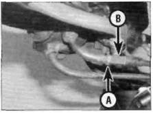
9 Make sure there is a small amount of freeplay in the cable before the plungers move. If there isn't, check that the cable is correctly installed at both ends - remove the fuel tank to access the carburettor end of the cable (see Chapter 4). To adjust, slacken the choke outer cable bracket screw on the carburettor and slide the cable further into the bracket, creating some freeplay (see illustration).Otherwise, renew the cable.
15 Carburettors-
synchronisation ^
| A |
Warning: Petrol (gasoline) is extremely flammable, so take extra precautions when you work on any part of the fuel system. Don't smoke or allow open flames or bare light bulbs near the work area, and don't work In a garage where a natural gas-type appliance is present. If you spill any fuel on your skin, rinse it off immediately with soap and water. When you perform any kind of work on the fuel system, wear safety glasses and have a fire extinguisher suitable for a Class B type fire (flammable liquids) on hand.
| A |
Warning: Take great care not to burn your hand on the hot engine unit when accessing the gauge take-off points on the inlet manifolds. Do not allow exhaust gases to build up in the work area; either perform the check outside or use an exhaust gas extraction system.

|
| 14.9 Choke cable bracket (A) and screw (B) |
1Carburettor synchronisation is simply the process of adjusting the carburettors so they pass the same amount of fuel/air mixture to each cylinder. This is done by measuring the vacuum produced in each cylinder. Carburettors that are out of synchronisation will result in decreased fuel mileage, increased engine temperature, less than ideal
throttle response and higher vibration levels. Before synchronising the carburettors, make sure the idle speed is correct (see Section 2) and that the valve clearances are properly set (see Section 26).

|
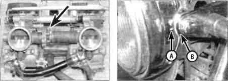
| 15.6 Fuel tap vacuum hose union on I cylinder inlet manifold (arrowed) |
2 To properly synchronise the carburettors, you will need a set of vacuum gauges or calibrated tubes (manometer) to indicate engine vacuum. The equipment used should be suitable for a two cylinder engine and come complete with the necessary adapter and hoses to fit the take-off points. Note:Because of the nature of the synchronisation procedure and the need for special instruments, most owners leave the task to a Honda dealer.
3 Start the engine and let It run until it reaches normal operating temperature, then shut it off.
4 Remove the fuel tank (see Chapter 4).
5 Displace the coolant hose and remove the blanking screw from the vacuum take-off point on the inlet manifold of No. 2 cylinder. Install the take-off adapter provided with the vacuum gauges.
6 Connect the vacuum gauge hoses to the inlet manifolds of both cylinders - the right gauge hose connects to the take-off adapter provided and the left gauge hose connects to the stub on the No. 1 cylinder manifold which the tap vacuum hose normally connects to (see illustration).Make sure they are a good fit because any air leaks will result in false readings.
7 Arrange a temporary fuel supply to the carburettors. Ensure the fuel supply is above the level of the carburettors.
Every 8000 miles 1.15
|
Date: 2016-01-14; view: 933
| <== previous page | | | next page ==> |
| B ... and separate the plug from the tool | | | SW, SX and SY models |