CATEGORIES:
BiologyChemistryConstructionCultureEcologyEconomyElectronicsFinanceGeographyHistoryInformaticsLawMathematicsMechanicsMedicineOtherPedagogyPhilosophyPhysicsPolicyPsychologySociologySportTourism
Defining Hub Attachments
You can now define the hub bearing revolute joint between the wheel carrier and the hub.
To define the hub attachment:
1) Create a revolute joint as follows:
Ÿ Joint Name: hub_bearing
Ÿ I Part: ._macpherson.gel_wheel_carrier
Ÿ J Part: ._macpherson.gel_hub
Ÿ Joint Type: revolute
Ÿ Active: always
Ÿ Coordinate Reference: ._macpherson.ground.hpl_wheel_center
Ÿ Orientation Dependency: Delta orientation from coordinate
Ÿ Construction Frame: ._macpherson.ground.cfl_hub_bearing
2) Select OK.
Defining Suspension Parameters
You create a steering axis using the geometric method for calculating steer axes. When using the geometric method, ADAMS/Car calculates the steer axis by passing a line through two non-coincident hardpoints located on the steer axis. To use the geometric method, you must identify the part(s) and two hardpoints that fix the steer axis.
To create a steer axis:
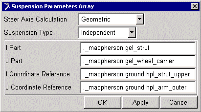
1) From the Buildmenu, point to Suspension Parameters,point to Characteristic Array, and then select Set.
2) Fill in the dialog box as shown next, and then select OK.

Creating a Suspension Subsystem
In this section, you create an ADAMS/Car suspension subsystem that is based on the template you just built. You also modify some hardpoints and translate the subsystem to ensure that ADAMS/Car correctly positions the subsystem within the assembly.
To create a subsystem:
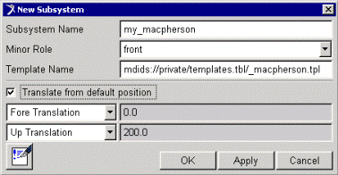
1) From the Filemenu, point to New,and then select Subsystem.
2) Fill in the dialog box as shown next, and then select OK.

ADAMS/Car displays the following message: The template _macpherson exists in memory. Do you want to use it?
3) Select Yes.
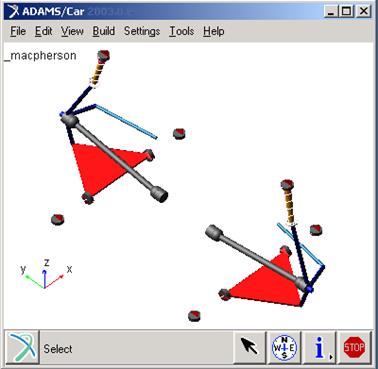
ADAMS/Car displays the subsystem.

To modify hardpoints:
1) From the Adjustmenu, point to Hardpoint,and then select Table.
2) Modify the hardpoint values to match those listed in Table 8.3:
Date: 2015-12-18; view: 1245
| <== previous page | | | next page ==> |
| Types of Suspension Analyses | | | Animating the Results |