CATEGORIES:
BiologyChemistryConstructionCultureEcologyEconomyElectronicsFinanceGeographyHistoryInformaticsLawMathematicsMechanicsMedicineOtherPedagogyPhilosophyPhysicsPolicyPsychologySociologySportTourism
Rear Delivery Spreaders
The heavy duty steel floor has an endless chain and slat conveyor which moves the manure to the rear of the spreader. Here, high speed shredders or beaters tease out and spread the manure to a width of 6-14 m (20-45 ft). Some high-capacity machines have spreading widths of up to 24 m.
Various types of spreading mechanism are used. Some machines have a single horizontal rotor, which may be a spiked rotor or an auger with left- and right-hand flights to shred and spread the manure. Other models have two or three horizontal rotors for this purpose.
Another design has vertical spreading rotors - two, three or four in number - spaced across the back of the machine. The moving floor conveyor and spreading mechanisms may be driven by the power take-off, protected with an overload slip clutch or by a variable speed hydraulic motor supplied with oil from the tractor hydraulic system.
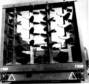
Figure 12.2 Four vertical rotors shred and spread manure carried to them by a twin chain and slat floor conveyor.

Figure 12.3 Rear view of a horizontal beater manure spreader
Rear delivery spreaders are best suited to manure with a high straw content, but some models can be adapted for use with slurry and chicken litter. A rear gate or slurry door, raised and lowered by hydraulic rams, restricts the flow of semi-liquids to the spreading rotors. A special chicken litter attachment can be used on some models of manure spreader with a horizontal spreading rotor. It consists of a row of spinning discs, usually four in number, under a large metal cover. The rotor feeds the litter at a controlled rate to the hydraulic motor driven discs which spread it over a wide area.
Capacities usually range from 5 to 24 tonnes of farmyard manure. Some spreaders have a load cell under the body which measures the weight of the load. Application rates will vary from about 1 tonne up to 50 tonnes per hectare (20 tons/acre).
When loading a rear delivery manure spreader, fill the front first and it will be easier to manoeuvre the tractor and loader if the spreader is set at an angle of about 30 degrees to the heap.
Drive engagementThe power take-off lever on the tractor engages drive to the floor conveyor and shredding mechanism on power driven models and the auxiliary services valve controls oil flow to the hydraulic motor.
Application rateis altered by changing the speed of the moving floor conveyor with a lever or screw adjuster on power take-off driven models or by varying oil flow on spreaders with a variable speed hydraulic motor. Tractor forward speed, altered with the gearbox, also changes the application rate. A low forward speed and high floor conveyor speed gives a high application rate.

Figure 12.4 A rear beater farmyard manure spreader equipped with doors and a spinning disc for spreading slurry.
Rotary Spreaders.
The open sided cylinder shaped trailer body or drum of a rotary sidespreader makes it ideal for handling very wet materials as well as farmyard manure. A number of high speed flails attached to a centrally mounted rotor by heavy chains throw the manure from the side of the spreader onto the ground. The rotor shaft is driven by a chain and sprocket reduction unit from the power take-off. Rotor speed is varied by fitting different size sprockets to the chain drive, which is protected by an overload safety clutch.
When starting to spread with a full load only the outer flails distribute the manure. Before the spreader is filled the flails should be wrapped around the rotor. When spreading commences with a full load, the flails at each end of the rotor distribute the manure and as the load is discharged more of the flails are able to swing free and gradually empty the spreader from both ends towards the centre. A hinged lid above the drum, operated with a hand lever or a hydraulic ram, is opened to facilitate filling.

Plate 12.5 The arrangement of the flails on a rotary manure spreader.

Figure 12.1 Sectional diagram of a rotary manure spreader.
Rotary manure spreaders are made in various sizes with capacities from 3-12 tonnes or approximately 1,200-4,800 litres and a spreading width of 3-12 m depending on the size of the machine. Application rates are within a range of 12-60 tonnes per hectare (5-25 tons per acre) depending on model, but this can be increased with a second dressing.
Drive engagement.The tractor power take-off lever engages drive to the flail rotor.
Application rateTractor forward speed, changed with the gearbox, varies the quantity of manure spread per hectare. When selection of different forward speeds fails to give the required dressing, the flail speed can be changed by fitting different sized sprockets on the chain drive to the rotor shaft. Flail rotor speeds vary between 200 and 350 rpm depending on model.
Side spreaders
An auger in the bottom of a triangular section hopper carries manure to a paddle bladed rotor which throws the manure sideways from the spreader. The paddle rotor is near the front on юте models; others have a more central rotor. The auger has left- and right-handed flights which carry the manure to the spreading mechanism, from where it is thrown up to 15 m or more. The auger and spreading rotor drives nave shear bolts to protect them from damage if either mechanism is overloaded. An adjustable gate which controls the flow of manure to the spreading mechanism is opened and closed with a hydraulic ram.
Sidespreaders are multi-purpose machines and require a tractor of at least 60 kW (80 hp). They can be used to spread farmyard manure, slurry or poultry litter and have a capacity of up to 15 tonnes of manure or approximately 13,000 litres (2,800 gallons) of slurry.
Application rateis changed by varying the tractor forward speed, internal auger speed and by opening or closing the adjustable shutter, which controls flow of material from the hopper. The shutter position will vary considerably depending on the type of material being spread.
Using manure spreaders.Best results are obtained with rear spread machines by working in strips or lands. This will avoid undue idle running on the headlands. With side delivery spreaders, it is necessary to start at one side of the field and work across to the other. A tractor with a pick-up hitch makes one-man operation very easy. The driver can load his spreader with a tractor-mounted loader, then hitch up and spread the load without leaving the tractor seat.
On the larger farms, one man may use the loader while a second uses two spreaders.
Spreader maintenance.Except for sealed bearings, all lubrication points should be greased daily when the machine is in use. Gearbox oil levels should be checked frequently and chain drives kept correctly tensioned. Check the condition of the oil pipes and connector on machines with hydraulic motor drive.
At the end of the season the machine should be thoroughly washed and damaged parts replaced. It is good practice to protect the spreader from corrosion with a rust preventative or waste oil.

Plate 12.6 This sidespreader with a power take-off driven auger and spreading rotor holds about 9 tonnes of manure.
Slurry spreaders
Slurry can be spread with specialist irrigation equipment using a pump, pipeline and slurry guns which spray the liquid onto the land. More often, slurry spreaders which load, transport and spread the material are used. Most slurry spreaders have a cylindrical shaped tank, but others are rectangular, with capacities from 3,500-13,500 litres. The larger machines are mainly used by contractors. Environmental considerations have led to an increase in the use of injection equipment, which deposits the slurry in slots cut in the soil by tines on a rear-mounted bar.
There are several types of slurry tanker. Some are filled with a vacuum pump on the machine and others use a mechanical filling system. Some tankers are top filled by a slurry pump which is usually part of a handling and mixing system at the slurry store.

Plate 12.7 A slurry spreader.
Vacuum tankershave a high capacity power take-off driven vacuum pump which draws the liquid through a pipe placed in a slurry storage tank, pit or lagoon. When the tank is full, the pump is used to pressurise the contents to about 3 bar (45 psi). This pressure is used to expel the slurry from the tank when the rear discharge spout is opened. A deflector plate behind the spout spreads the slurry in a band up to 20 m wide. Some machines can have a slurry gun mounted near the top of the tank which receives the pressurised liquid and applies it to the soil.
Application rate is varied by changing the forward speed of the tractor or altering the position of the deflector plate to change the width of spread.
Open top tankersare top filled by a separate mechanical slurry pump and spread from the rear discharge nozzle by an internal, power take-off driven impeller pump. Some spreaders are emptied by gravity and the slurry is spread by a power driven spinning disc under the outlet pipe.
Another type of slurry spreader which does not have a vacuum pump is filled by reversing it down a ramp into a slurry lagoon. A power take-off driven impeller pump at the rear draws slurry into the tank and fills it in less than five minutes. The same pump is used to spread the slurry from a spout near the top of the tank. The spout can also be used to re-circulate the slurry to stir the contents of the lagoon and break up surface crusts. Hydraulic controls enable the tractor driver to fill the tank and spread its contents without leaving the seat.

Plate 12.8 The auger on this slurry spreader is used to fill the tank
after it has been reversed down a suitable ramp part way into a slurry lagoon.
Output.Slurry spreaders can run over the same area several times, so output is best measured in the time taken to fill and empty the machine. A typical 4,500 litre tank can be both filled and emptied in 3-5 minutes.
Slurry mixers.Some slurry tankers can be used to pump the material back into the storage tank, pit or lagoon to break up surface crusts or mix liquids and solid matter. This operation can also be done with a tractor-mounted mixer with a power take-off driven propeller.
The standard machine with a 5 or 7 m arm for mixing the contents of open lagoons or pits can be raised and lowered mechanically or with a hydraulic ram to stir the slurry at different levels. Other versions are used to stir the contents of slurry storage tanks. One model, attached to the top of a three-point linkage mounted mast, has a propeller which can be lowered into slurry tanks with sides up to 5 m high with a hydraulic ram. Another design has a power take-off driven propeller permanently installed in the lower part of the storage tank. When the contents require mixing, the drive shaft is attached to a tractor power take-off and left to do its work.

Plate 12.10 This slurry tanker with a four-leg slurry injector has a working width of 2.5 m.

Plate 12.9 Power take-off driven slurry mixer.

Plate 12.11 Spring-loaded tines for shallow injection of slurry, usually into grassland. About 20 of these tines on a rear-mounted toolbar give a working width of approximately 5 m.
Slurry injectors.Slurry injection equipment has helped to overcome some of the complaints from the public about air pollution when spreading slurry. A frame mounted on the back of the slurry tank carries a number of tines which cut slots in the soil, and slurry, pumped through flexible tubes attached to the tines, is deposited in these slots. Widely spaced, heavy duty subsoiler-type tines as seen in Plate 12.10 are normally used to inject slurry into arable land. Much lighter tines at narrower spacings, as shown in Plate 12.11, which make much shallower slots, are usually preferred for grassland. The tank contents are pressurised to a sufficient degree to carry the slurry along the pipes to the ground, where it is injected into slots from 30-150 mm deep depending on the soil surface and type of tine.
Date: 2015-12-17; view: 1788
| <== previous page | | | next page ==> |
| Manure and fertiliser distribution machinery | | | Spinning disc broadcasters |