CATEGORIES:
BiologyChemistryConstructionCultureEcologyEconomyElectronicsFinanceGeographyHistoryInformaticsLawMathematicsMechanicsMedicineOtherPedagogyPhilosophyPhysicsPolicyPsychologySociologySportTourism
E. PID Controlled Cruise Control
PID stands for Proportional Integral Derivative. It uses 3 types of controls that can each be fine tuned to get the perfect response. Adding a PID makes the system look like this (Figure 6):
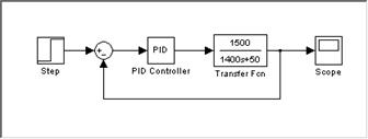
Fig. 6. Simple PID controlled closed loop cruise control block diagram.
If a PID controller simply has the Proportional component set at 1, it does nothing, and the output of the system is identical to that of the previously looked at feedback loop with the steady state error of 1 m/s. Adding an integral component set at 1 introduces some undesirable overshoot to the system and also increases the response time, but does solve the steady state error problem—the output is now at the desired 30 m/s (Figure 7):

Fig. 7 PID controlled closed loop cruise control system response;
P=1, I=1, D=0.
Adding the derivative component set at 1 makes the oscillations ever wilder at the beginning, both increasing the overshoot and increasing the response time. However, what it does do is get rid of and of the long term oscillations seen in the previous response (Figure 8):
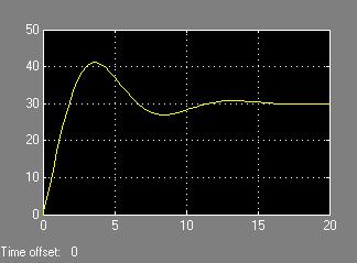
Fig. 8 PID controlled closed loop cruise control system response;
P=1, I=1, D=1.
Now the response must be fine tuned by tinkering with the different values of the PID. As it is right now, the settling time is reasonable for the 15 second acceleration target, and the rise time is probably even a bit fast. The big problem that must be fixed is the large overshoot. Imagine pressing a button that you thought would make your car accelerate to 65 mph and having the car shoot all the way up to over 80 mph first! This would simply not be allowed to happen in a real automobile.
It should be mentioned that it is not necessary to utilize all three components of a PID in all cases. In situations where a very fast rise time is needed, all three components can be very important, in order to control the settling time and overshoot. However, in a slow rise time situation such as this one, it is possible to control the overshoot, steady state error, and response time with just two of the components. This is because of the general effects each of the components has on the response. The proportional controller has a huge effect on rise time—the higher it is set, the quicker the response. However, increasing the proportional component also introduces some steady state error and often a fair degree of overshoot too. The integral controller also speeds of response time, and has potential to increase the overshoot too; however, its most useful attribute is that it helps to eliminate steady state error. The purpose of the derivative controller then becomes cutting down on the overshoot caused by the proportional and integral.
With these factors in mind, let’s now revisit the cruise control response starting again with just the proportional response. Recall that with the proportional controller set to 1, the car accelerated to the desired speed in about 5 seconds, but also had a steady state error the left the final speed slightly below the desired level. Since 5 seconds is too quick for average driving conditions, decreasing the proportional controller should help slow the response. With the proportional controller set to 0.3, the response becomes the following (Figure 9):
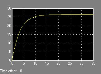
Fig. 9 PID controlled closed loop cruise control system response;
P=0.3, I=0, D=0.
This has a nearly perfect acceleration time of about 15 seconds. However, the steady state error has increased negatively again, and the car now is traveling significantly slower than desired. Adding the integral controller should help fix this steady state error. However, we know that using too high of a value for the integral controller can create much overshoot and an undesirable level of oscillation, so the integral value must be set very small to find the optimum point of eliminating steady state error while not created any overshoot. A value of 0.01 appears to do this very nicely (Figure 10):
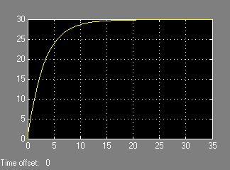
Fig. 10 PID controlled closed loop cruise control system response;
P=0.3, I=0.01, D=0. This shows a reasonably desirable acceleration of an average car.
This appears to exactly fulfill what the design specifications wanted without even using a derivative controller. The derivative is not needed here simply because the slow response time means that neither the proportional nor the integral controllers need to be set at a level that creates any overshoot.
Through this demonstration of how a PID can be used to tune a cruise control system, one can see how the system could then be tuned for different vehicles that drive in different ways. This 15 second response might be good for a minivan or family sedan, but a driver of a sports car might wish for a much quicker response time from the cruise control system. Setting the proportional and integral controllers to values of 0.6 and 0.02, respectively, creates such an output (Figure 11):

Fig. 11 PID controlled closed loop cruise control system response;
P=0.6, I=0.02, D=0. This shows a reasonably desirable acceleration of a sports car.
It is easy to see from this how a PID is extremely versatile for tuning a cruise control system exactly to the desired automobile specifications.
 F. Disturbance
In real world driving conditions, a cruise control system generally has to work at maintaining a constant speed as well as accelerating to the correct speed. In fact, the ability to maintain the proper speed is probably more important to the customer’s satisfaction with the cruise control system than the ability to accelerate well. Factors like wind, hills, varying road friction, drafts from other vehicles, or steering forces all work against the speed of the vehicle—some work to speed it up, and some work to slow it down. This sort of idea could probably be modeled with some sort of random signal generator disturbance input in the system, but a more complicated would need to be created to actually show how the system would operate. To do this topic justice, a whole separate paper would need to be
devoted to it. This paper will
stick more with the fundamentals.
G. Real World Systems
Real world cruise control systems, while built around many of the basic principles already discussed, are vastly more complicated than just a PID controller feedback loop. While this type of control unit might actually still be utilized somewhere in the cruise control logic, there likely exists a much more complicated logic system with multiple loops feeding back to various points in the system.
To compare the way a real world system is set up, some technical diagrams from a cruise control system in a 1991 Dodge Stealth were found. While these diagrams are not from a new car of the last few years, they still effectively can give a glimpse into both the complexity and the fundamentals of a real world system (it even could be argued that these are a better starting point for analyzing real world systems, because new cruise control systems grow more complex with each new redesign).
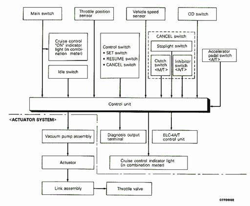
To start with, a diagram of the component structure of the Stealth cruise control system is shown in Figure 12. Since the beginning of the paper discussed the physical components that make cruise control work, this is a good place to start for looking at a real world system. In the diagram, all of the inputs to the system are shown above the control computer, and all of the outputs are shown below. Every component discussed previously in Section B is present in this system, and this diagram makes it very easy to see how each component fits into the system.
Fig. 12: Dodge Stealth Cruise Control Component Diagram.
The top half of the system (above the dotted zigzag line) is referred to as the control system, because its job is to work to actually tell the car what to do. One interesting part to note in the control system is the Throttle Position Sensor. This sensor, which is not mentioned in section B, monitors how far open the throttle is. By using both this and the vehicle speed as inputs, the computer is able to make better decisions about how aggressively to open or close the throttle in order to make the car travel at the desired speed; it allows for smoother operation of the system. If the car is losing speed, the computer needs to send the message to open the throttle wider. Having a sensor on the throttle allows for this to be done smoothly—rather than opening the throttle very rapidly and creating a jerky ride (the exact problem that led Teetor to invent cruise control in the first place), the throttle position sensor lets the computer know to ease onto the throttle to maintain a more steady response of the vehicle.
Two other control components worth noting are the overdrive switch (OD switch) and the ELC-4A/T control unit. One worry that exists in a car with overdrive is that the overdrive gear, which is usually the gear being used while cruise control is on, will not allow the car to have enough power to climb hills. Depending on gearing and engine output, some cars are not able to maintain speed on a hill with overdrive engaged. In a car with a manual transmission, it would be up to the driver to shift out of overdrive and into a lower gear; on a car with an automatic transmission, it is possible for the cruise control system to monitor when this needs to be done, and actually do it. The OD switch simply senses whether overdrive is engaged; if the computer senses a significant decrease vehicle speed sensor’s speed reading (4 mph), it will send a signal to the transmission control unit to shift out of overdrive and into third gear. To avoid a gear hunting problem, which would mean the transmission continually is shifting back and forth between third and overdrive, the computer tells the transmission to hold third gear for a fixed amount of time to assure that the vehicle has time to get back to speed rather than having the transmission quickly shift back to overdrive as soon as the speed begins to increase.
 The bottom half of the system (below the dotted zigzag line) is called the actuator system. This part of the system takes an output signal from the control computer and turns it into mechanical motion through a series of actuators and linkages that connect to the throttle. The actuator system found in this Stealth has no significant differences compared to the one described in Section B.
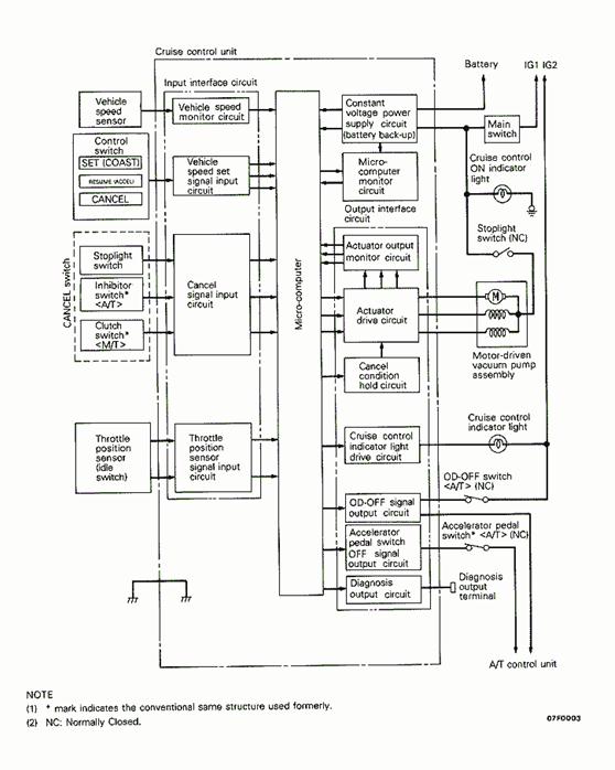
One area that is still very grey in this Dodge Stealth cruise control system in this is control computer. To help clear up somewhat how it works, a logic diagram is shown in Figure 13. Unfortunately, this diagram still does not dig into the actual logic process used inside the computer, but rather just gives a much more detailed look at how the inputs and outputs are integrated into the computer. However, it does show some of the feedback loops that
are present in the overall system.
The way Figure 12 was arranged, one might think that the system operated like an open loop system; the vehicle speed sensor
and the throttle position sensor both fed inputs into the computer, but nothing on the output side of the computer was shown to be monitored and fed back into the computer. However, a careful look at this logic diagram in Figure 13 shows that there is some feedback monitoring taking place with the control computer. Both the micro-computer monitor circuit and the actuator drive circuit send information back into the computer. The purpose of the loop on the micro-computer monitor appears to simply be to keep checking to make sure the power supply to the micro-computer is working properly. The feedback loop on the actuator drive circuit appears to actually function similar to the way the feedback Fig. 13. Dodge Stealth Cruise Control Logic Diagram
loop in the simulink simulations worked; that is, it monitors what the controller is doing, and uses this data to decide what else needs to be done. Unfortunately, as mentioned already, there is really no further information on the nature of the control computer in this system.
H. Conclusions
Cruise control technology has come a long way since the first systems invented by Teetor or installed on the late 50’s Chryslers. With the glimpse into the real world Dodge Stealth system from 1991, it is easy to see just how much computerized control play a role in controlling the speed of vehicles today. As computerized control technology continues to expand, it is expected that adaptive cruise control will begin to become more widespread. The possibilities of what such a system can do seem nearly limitless. If every car on the road could one day be equipped with adaptive cruise control, we could live in a world with drastically fewer traffic accidents than we ever have thought possible. While cruise control was invented as a comfort or convenience item, it could eventually begin to double as a safety feature that changes the way we drive our cars.
Date: 2014-12-22; view: 4530
| <== previous page | | | next page ==> |
| D. Simple Block Diagram Simulations | | | V. Biography |