CATEGORIES:
BiologyChemistryConstructionCultureEcologyEconomyElectronicsFinanceGeographyHistoryInformaticsLawMathematicsMechanicsMedicineOtherPedagogyPhilosophyPhysicsPolicyPsychologySociologySportTourism
Thevenin’s Theorem and Maximum Power Transfer
Introduction
A two terminal network resistive network can be replaced by a voltage source in series with an equivalent resistor. The value of the source voltage equals the open circuit voltage of the two terminals under consideration. The value of the equivalent resistor equals the resistance measured between the open terminals when all the sources of the circuit are deactivated (voltage source shorted and current source opened). This is termed as the Thevenin’s theorem. The voltage source is called Thevenin’s voltage (VTH) and the equivalent resistor, the Thevenin’s resistance (RTH).
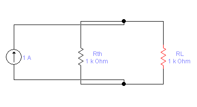
The maximum power output to a variable output resistance occurs when the value of the outputresistance equals the Thevenin’s resistance.
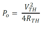
Figure 1: Maximum power output condition
The value of the maximum output power or transferred power is given as,
Objectives
1. To construct Thevenin’s equivalent using Workbench.
2. To verify the equivalent obtained in step 1 using hardwired components.
3. To determine maximum power transfer condition experimentally.
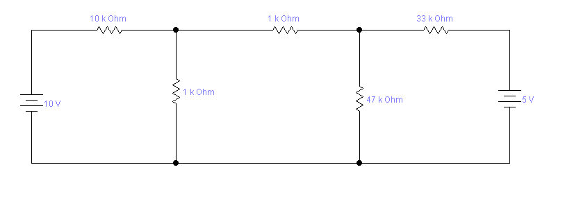
Step 1: Construct the circuit given in Figure 2 on Multisim Electronics Workbench.
Step 2: Remove the load resistor RL and connect a multimeter (or voltmeter) to read the open circuit voltage between A and B. Simulate and record the voltage. This is VTH for this circuit between A and B. 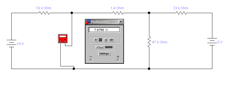
Step 3: Remove the 10-V source. Replace it by a short circuit.
Step 4: Remove the 5-V source. Replace it by a short circuit.
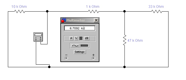
Step 5: Connect a mutimeter in the resistance measurement mode between A and B. Run the simulation and record the value of the resistor. This is RTH in Figure 1.
Table 1: Simulation results for Thevenin’s voltage and resistance
| VTH | RTH | |
| Simulated Measurements | 7.6758V | 6.7092kOhm |
Step 6: In the circuit of Figure 2 connect a variable resistor (RL) between A and B. 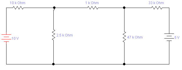
Step 7: Vary RL between 2.5 kOhm to 10.5 kOhm in steps of 1 kOhm . Measure voltage between A and B (VL) in each case. Enter your results in Table 2.
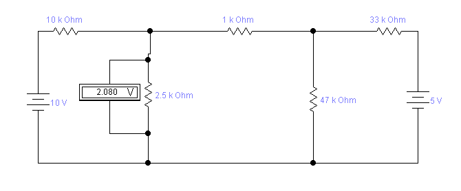
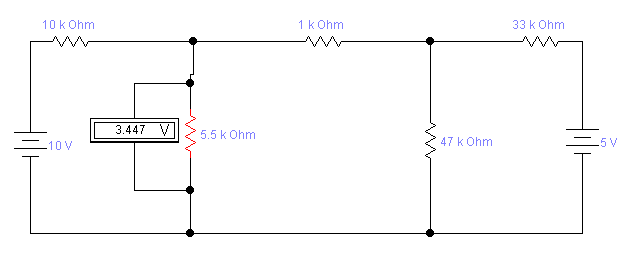
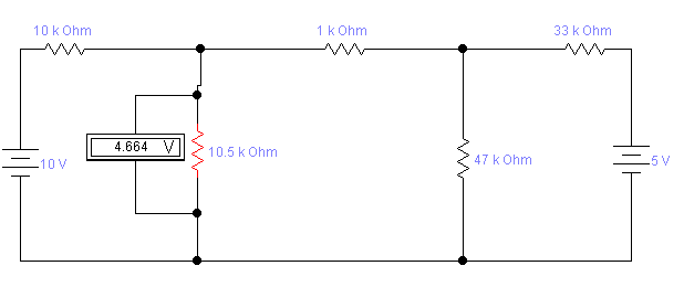
Table 2: Measured results for maximum power transfer
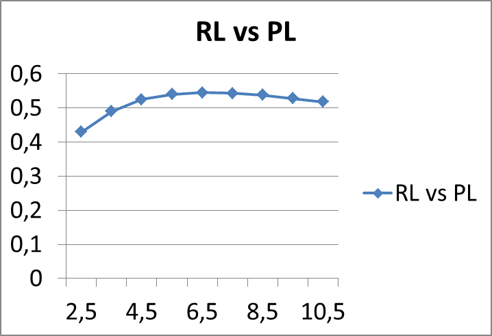
| RL(kOhm ) | 2.5 | 3.5 | 4.5 | 5.5 | 6.5 | 7.5 | 8.5 | 9.5 | 10.5 |
| VL | 2.080 | 2.625 | 3.073 | 3.447 | 3.765 | 4.037 | 4.274 | 4.481 | 4.664 |
| PL | 0.43 | 0.49 | 0.525 | 0.54 | 0.545 | 0.543 | 0.538 | 0.528 | 0.518 |
Step 8: Plot RL vs. PL
Questions:
1) At what value of RL the maximum value of PL occurs in the graph?
At RL=6.5kOhm the value of PL is maximum
2) How does this value of RL compare with RTH you obtained through Workbench?
3) Draw the Norton’s equivalent of the circuit in Figure 1.
4) Suppose you did not know the Thevenin’s equivalent circuit, what procedure would you follow in the laboratory to get the Norton’s equivalent?
Date: 2015-02-03; view: 5433
| <== previous page | | | next page ==> |
| NON-SEMANTIC GROUPINGS | | | Lecture 6 Newspaper Article Interpretation |