CATEGORIES:
BiologyChemistryConstructionCultureEcologyEconomyElectronicsFinanceGeographyHistoryInformaticsLawMathematicsMechanicsMedicineOtherPedagogyPhilosophyPhysicsPolicyPsychologySociologySportTourism
Ripple Counters
A ripple counter uses edge-triggered cells connected in such a way that the clock input of the cells does not correspond to the clock signal but to the output of another cell. That is, the change in the output of one cell triggers the change of another cell. We first give an example and then develop more of the characteristics of these counters.
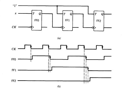
Consider the network of Figure 2.52a. It consists of three T flip-flops connected in such a way that the output of one flip-flop goes to the clock input of another. Assume that the flip-flops are trailing-edge triggered.
When x=0, the input T of FF0 is 0 and the flip-flop does not change during the clock period. As a result of this, no transition occurs in the clock input of FF1 and this flip-flop does not change either. The situation is similar for FF2, so that the counter state remains the same.
The timing diagram of Figure 2.52b illustrates the operation of the network when x=1. Assume that initially the state of the three flip-flops is 000. When the clock input changes from 1 to 0, a negative transition appears at the clock input of FF0 and it changes state. The output of this flip-flop goes from 0 to 1, producing a positive transition on the clock input of FF1, and this flip-flop does not change state. No transition occurs, therefore, at the output of FF2 and this flip-flop does not change state. Consequently, the new state is 001.
The network remains in state 001 until another negative transition (from 1 to 0) occurs in the clock input. When this happens, FF0 changes state from 1 to 0. Therefore, its output has a negative transition that appears at the clock input of FF1 and this flip-flop changes state from 0 to 1. Since its output has a positive transition. FF2 does not change. The new state is 010.

Fig. 2.52 - (a) A modulo-8 ripple, (b) Timing diagram (x=1).
The sequence of events just described indicates why the network is called a ripple counter: the changes ripple through the flip-flops. The negative edge of the clock produces the change of state of FF0, and this change produces the change of state of FF1. This implies that this counter is not synchronous since all flip-flops do not change simultaneously with the change in the clock.
The process continues as indicated in Figure 2.52b. It can be seen from there that the network implements a modulo-8 binary counter.
In general, a modulo-2n ripple counter has n flip-flops connected as in Figure 2.53 FF(k) changes state when FF(k-1) changes from state 1 to state 0, which occurs when FF(k-1) was in state 1 and FF(k-2) changes from 1 to 0, which, in turn, occurs when FF(k-2) was in state 1 and FF(k-3) changes from 1 to 0, and so on. Consequently, FF(k) changes when all previous flip-flops were in state 1 and change from 1 to 0.

Fig. 2.53 - A modulo-2” ripple counter.
From Figure 2.53 it is apparent that the ripple implementation results in a simple network since it consists of a very regular connection of the T flip-flops without any additional gate needed. However, it has the drawbacks that follow.
As mentioned, the ripple counter is not synchronous since the changes of the various flip-flops do not occur at the same time and are, therefore, not synchronized by the clock signal. This may create a "glitch" problem. Consider the output z0=Q2'Q1'Q0' shown in Figure 2.54a and its timing diagram in Figure 2.54b. Due to the asynchronous changes of the outputs of FF2, FF1, and FF0, z0 is likely to have the undesired pulse shown. This pulse, called a "glitch", may or a may not have an undesirable effect on the system's behavior, depending on the use given to the output.
A second drawback is that the ripple counter is slow since the changes have to propagate through the counter, from one flip-flop to the next. If the transition delay of a flip-flop is td, the delay of the counter when all flip-flops change state is
delay(ripple) = ntd
which is proportional to n. This should be compared to the delay of the synchronous counter, which is where d is the delay of the combinational network.

Fig. 2.54 - Glith problem. (a) Network, (b) Timing diagram (x=1).
delay(synchronous) = (td + d)
Consequently, the synchronous counter is faster than the ripple counter and is simpler to use in a synchronous network. The advantage of the ripple counter is that the network consists only of the flip-flops without requiring additional gates. Also, the connections are very simple, a feature that might be attractive in a VLSI design. The large delay has to be taken into account when incorporating this counter in an otherwise synchronous network .
Date: 2015-01-12; view: 1883
| <== previous page | | | next page ==> |
| Asynchronous straight binary counter | | | Asynchronous BCD counter |