CATEGORIES:
BiologyChemistryConstructionCultureEcologyEconomyElectronicsFinanceGeographyHistoryInformaticsLawMathematicsMechanicsMedicineOtherPedagogyPhilosophyPhysicsPolicyPsychologySociologySportTourism
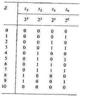
Asynchronous BCD counterThe table in Fig. 10.26 shows that a 3-bit counter can count up to 1 and a 4-bit counter up to 15. In a counter for straight BCD numbers, a 4-bit straight binary counter used as a decade counter is required for each decimal digit. This decade counter differs from the normal straight binary counter in that it is reset to zero after every tenth count pulse and produces a carry. This carry bit controls the decade counter for the next higher decimal digit. With BCD counters, a decimal display of the count is achieved much more easily than for the straight binary counter, as each decade can be separately decoded and displayed as a decimal digit. In straight BCD code, each decimal digit is represented by a 4-bit straight binary number, the bit weightings of which are 23, 22, 21 and 2°. It is therefore also known as the 8421 code. The state table of a decade counter employing 8421 code is shown in Fig. 2.55, By definition, it must be identical with that in
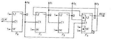
Fig.2.55 - State table for Fig. 2.56 - Timing diagram of the output 8421 code. states of an 8421-code counter. Fig. 2.40. up to the number 9, but the number ten = 10dec is represented again by 0000. The associated timing diagram for the output variables is shown in Fig. 2.56. Obviously, additional logic circuitry is required to reset the counter at every tenth input pulse. However, gates may be saved by using JK flip-flops with several J and K inputs, as in Fig. 2.57. In contrast to the normal straight binary counter, the circuit operates as follows: flip-flop F, may not change state at the tenth counting pulse, even though z0 changes from 1 to 0. From Fig. 2.42 we deduce a simple criterion for this case: Zj must be kept at 0 if z3 is 1 prior to the clock signal. To achieve this, the J input of F1 is connected to z3. The condition that z2 must remain 0 at the tenth pulse is therefore automatically satisfied.
Fig. 2.57 - Asynchronous BCD counter.
The second difference with respect to a straight binary counter is that z3 changes from 1 to 0 at the tenth pulse. However, if the clock input of F3 were connected to z2 as in a normal straight binary counter, z3 would be unable to change after the eighth counting pulse, since flip-flop Ft is disabled by thefeedback signal. The clock input of F3 must therefore be connected to the output of the flip-flop which is not disabled by the feedback signal, in this case z0. On the other hand, the J inputs must be controlled so that they prevent flip-flop F3 from changing state prematurely. Figure 2.55. indicates that z3 must not go to 1 unless both Zj and z2 are 1 prior to the clock signal. This may be achieved by connecting the two J inputs of F3 to z, and z2 respectively. Then, at the eighth counting pulse z3 = 1. Since z, and z2 become zero simultaneously, z3 resumes the state z3 = 0 as soon as possible, i.e. at the tenth counting pulse when z0 has its next transition from 1 to 0. Figure 2.55. indicates that this is precisely the right instant. 1C types: 4 bit 2 x 4 bit 74 LS 90 (TTL) 74 LS 390 (TTL) 10138 (ECL)
Date: 2015-01-12; view: 1399
|