CATEGORIES:
BiologyChemistryConstructionCultureEcologyEconomyElectronicsFinanceGeographyHistoryInformaticsLawMathematicsMechanicsMedicineOtherPedagogyPhilosophyPhysicsPolicyPsychologySociologySportTourism
Asynchronous straight binary counterA straight binary asynchronous (ripple) counter can be implemented by arranging flip-flops in a chain, as in Fig. 2.42, and by connecting each clock input C to the output Q of the previous flip-flop. If the circuit is to be an up-counter, the flip-flops must change their output states when their clock inputs C change from 1 to 0. Edge-triggered flip-flops are therefore required, e.g. JK master-slave flip-flops where J = K = 1. The counter may be extended to any size. Using this principle, one can count up to 1023 with only 10 flip-flops.
Fig. 2.42 - Asynchronous straight binary counter CLK = Clock RCO = Ripple Carry Output
Flip-flops triggered by the positive-going edge of the clock pulse can also be employed, e.g. single-edge triggered D flip-flops. If they are connected in the same way as in Fig. 2.42, down-counter operation is obtained. For up-counter operation, their clock pulse must be inverted. This is achieved by connecting each clock input to the Q-output of the previous flip-flop. Every counter is also a frequency divider. The frequency at the output of flip-flop F0 is half the counter frequency. A quarter of the input frequency appears at the output of Fj, an eighth at the output of F2, etc. This property of frequency division can be seen clearly in Fig. 2.41.
Counters A modulo-p counter is a sequential system with one binary input x and p states. The state diagram is shown in Figure 2.43. If the states are labeled with the integers 0, 1 , . . . , p-1, an arithmetic expression for the transition function is
s(t+1) = (s(t)+x) mod p
Fig. 2.43 - State diagram of a madulo-p-counter.
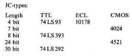
In most counter modules the output corresponds to the state. Also, usually an additional output is provided that has value 1 when the state is equal to p-1. This output, called terminal count, is useful to build larger counters. Counter modules differ in the number of states and in the code in which the output is represented by binary variables. We now define some of the most typical. The corresponding output codes are illustrated in Table 2.1. A binary counter has 2k states and k binary output variables that correspond to the binary representation of the integers 0 to 2k-1. A decimal counter has ten states and one decimal output variable. This output is coded on binary variables using a decimal code (e.g., BCD, Excess-3). Several of these codes have been defined. A Gray-code counter has 2k states and k binary output variables. The coding of the output is such that two time-consecutive outputs differ only in one binary variable. A ring counter has k states and k binary output variables. The output corresponds to the integers 0 to k-1 in a “1-out-of-k” code (one 1 out of k variables). It is called a ring counter because it can be implemented by a shift register with k cells in which the output of cell k-1 is connected to the input of cell 0 (Figure 2.44a).
Fig. 2.44 - (a) Ring counter, (b) Twisted-teil ring counter.
A twisted-tail ring counter has 2k states and k binary output variables. Its output code is illustrated in Table 2.1. It is called twisted-tail ring counter because it can be implemented using a shift register in which the complement of the output of cell k-1 is connected to the input of cell 0 (Figure 2.44b). Counters can count up or down. In an upward counter, state i is followed by state (i+1) mod p, while in a downward counter state i is followed by state (i-1) mod p. Up/down counters count both ways, the direction being determined by a control input. The main use of counters is the generation of counting sequences, and control and timing signals in digital systems. A typical MSI binary modulo-16 counter is shown in Figure 2.45. The output vector Q corresponds to the state (it is the binary representation of integer q). The input vector I is the binary representation of integer i. The control inputs are LOAD, CLEAR, and CE (count enable). CK is the synchronizing clock. The transition function is as follows:
Note that when LOAD= 1 the operation is LOAD even if CE= 1. The output TC (terminal count) is 1 during state 15 if CE=1, that is
Fig. 2.45 - A modulo-16 countres.
Similar MSI modules exist for decimal counters, up/down counters, and so on. We now describe several basic types of counters that can be easily constructed using a modulo-16 counter and gates. Of course, these counters can also be implemented using other modules, such as flip-flops and gates or a register and an adder, the advantage of the implementation presented here being its modularity. In a later section we consider the implementation of general sequential systems using the MSI counter. l. Modulo-n counter (1 £ n £ 16). The state diagram of this counter is shown Figure 2.46. Note the transient states Sn to S15. (Transitions for x = 0 not shown)
Fig. 2.46 - Modulo-n counter-(n<16). To obtain this type of operation, the LOAD input is used to achieve the transition from state n-1 to state 0, while the normal counting is used for the other transitions. Therefore,
which results in the switching expression
LOAD = mn-1(Q3, Q2, Q1, Q0)· x
where mn-1(Q) is the (n-l)th minterm of Q. The vector loaded through the input I is (0, 0, 0, 0). An example of a modulo-12 counter and its time behavior are shown in Figure 2.47.
Fig.2.47 - A modulo-12 counter and its time behavior.
2. a-to-b counter (0 £ a, b £ 15). The state diagram of an a-to-b counter is shown in Figure 2.48. The transition from state b to state a is done by loading the value a during state b, and using the COUNT ENABLE for the other transitions. This is accomplished by
which results in the switching expression
LOAD = mb(Q3, Q2, Q1, Q0)· x
An implementation of a l-to-12 counter is given in Figure 2.49. Note that the expression for LOAD can be simplified. For example, for the l-to-12 counter, LOAD=Q3· Q2· x.
Fig. 2.48 - An a-to-b counter.
Fig. 2.49 - A 1-to-12 counter.
3. Modulo-n divider (1 £ n £ l6). In this counter, the binary output y is 1 every nth occurrence of the event x= 1. The corresponding state diagram is shown in Figure 2.50.
Fig. 2.50 - Modulo-n-divider.
This type of operation is accomplished by taking the output from TC and loading the state 16-n when TC= 1. That is,
An implementation of a modulo-9 divider is given in Figure 2.51a. A segment of its time behavior is shown in Figure 2.51b.
Fig. 2.51 - A modulo-9-divider.
Date: 2015-01-12; view: 1806
|