CATEGORIES:
BiologyChemistryConstructionCultureEcologyEconomyElectronicsFinanceGeographyHistoryInformaticsLawMathematicsMechanicsMedicineOtherPedagogyPhilosophyPhysicsPolicyPsychologySociologySportTourism
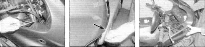
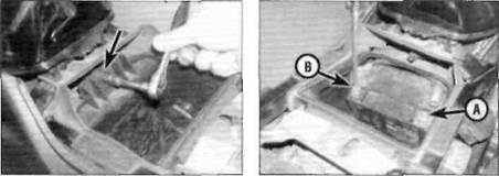
A Unscrew the nut (arrowed)7.1b ... and withdraw the turnsignal through the fairing Remove the storage box
7.3a Remove the screws from the mounting bracket... 7.3b ... andrelease thepegs (arrowed) from the lower edge of the fuel tank Lift the fairing forwards off the bike 8«4 Bodywork
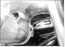
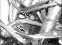
Fairing stay mounting bolts (arrowed) Fairing mounting bracket is retained by single bolt (arrowed)
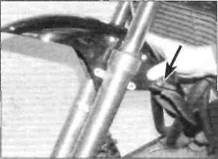
Lift the mudguard clear of the fork sliders. Speedometer cable guide arrowed
5The fairing is constructed in four sections; left and right-hand panels, front panel and windshield. The headlight unit is bolted onto the back of the front panel (see Chapter 9). The individual sections of the fairing can be separated for renewal or repair by unscrewing the connecting screws; the windshield screws are retained by nuts, the panel screws are retained by metal plates. Note the position of all screws on disassembly. 6 The fairing stay is mounted to the steering head by two bolts (see illustration).To remove the frame, first remove the instrument cluster (see Chapter 9) and unclip the wiring loom for the instruments and the headlight. Unscrew the frame mounting bolts and remove the frame. 7 The two fairing mounting brackets on the front edge of the fuel tank can be removed by unscrewing the mounting bolts (see illustration). Installation 8Installation is the reverse of removal, noting a) If removed, do not overtighten the fairing panel screws, especially the windshield screws. b) Make sure the wiring looms are secured to the fairing stay. c) When installing the fairing, ensure the two pins on the back of the headlight unit bracket locate in the grommets on the front lower edge of the fairing stay.
d) Install the glove box only after the fairing has been installed. e) Make sure the wiring connectors are securely connected. 9 Turn the handlebars from lock to lock to 10 Test the operation of the lights before ■ removal and installation Removal 1 Remove the front wheel (see Chapter 7) and pull the speedometer cable out of the cable guide on the front mudguard. 2 Remove the four bolts securing the mudguard to the fork sliders and remove the mudguard by lifting it up between the fork legs and withdrawing it forwards (see illustration). 3A metal plate inside the mudguard retains four mounting nuts; only remove the plate if it is damaged and must be renewed. 4 The speedometer cable guide is a push fit in the left-hand side of the mudguard (see illustration 8.2). Installation 5 Installation is the reverse of removal, noting a) Route the speedometer cable through the cable guide. b) Secure the front brake hose clamp with the rear right-hand mudguard mounting bolt. c) Tighten the mudguard mounting bolts to the torque setting specified at the beginning of this Chapter. 9«1 Chapter 9 Electrical system Contents Alternator - removal, inspection and installation........................ 32 Battery - charging........................................................................... 4 Battery - removal, installation, inspection and maintenance ... 3 Brake light switches - check and replacement............................ 11 Brake/tail light bulbs - test and renewal ....................................... 9 Charging system - leakage and output tests ............................. 31 Charging system testing - general information and precautions ... 30 Clutch switch - check and replacement....................................... 22 Diode - check and replacement .................................................. 23 Electrical system - fault finding..................................................... 2 Fuses - check and renewal........................................................... 5 General information....................................................................... 1 Handlebar switches - check.......................................................... 24 Handlebar switches - removal and installation........................... 25 Headlight aim - check and adjustment ...................... see Chapter 1 Headlight and sidelight bulbs - test and renewal ...................... 7 Headlight assembly - removal and installation........................... 8 Horn - check and replacement...................................................... 26 Degrees of difficulty Ignition (main) switch - check, removal and installation........... 18 Ignition system components ..................................... see Chapter 5 Instrument and warning light bulbs - renewal.............................. 17 Instrument cluster and speedometer cable - removal and installation............................................................. 15 Instruments - check and replacement ......................................... 16 Lighting system - check ............................................................... 6 Neutral switch - check, removal and installation ...................... 20 Oil pressure switch - check, removal and installation................ 19 Regulator/rectifier - check and replacement................................ 33 Sidestand switch - check and replacement ................................ 21 Starter motor - disassembly, inspection and reassembly........... 29 Starter motor - removal and installation....................................... 28 Starter relay - check and replacement ......................................... 27 Tail light assembly - removal and installation............................. 10 Turn signal bulbs - test and renewal............................................. 13 Turn signal assemblies - removal and installation ................... 14 Turn signal circuit - check............................................................. 12
Easy,suitable for novice with little experience Fairly easy,suitable ^ for beginner with <^ some experience !|S
Fairly difficult, suitable for competent J^; Difficult,suitable for ^ experienced DIY 2^ mechanic
Very difficult, suitable for expert DIY ^ Specifications Note:Where applicable, models are identified by their production code letter - refer to 'Identification numbers' at the frontof this manual for details. Battery Capacity............................................................................................... 12V, 8Ah Voltage Fully charged @ 20°C..................................................................... over 13.0V Discharged @ 20°C......................................................................... below 12.3V Charging rate Normal ........................................................................................... 0.9A for 5 to 10 hrs Quick .............................................................................................. 4.0A for 1 hr Charging system Current leakage ...................................................................................... 1mA (max) Regulated voltage output......................................................................... 14.0 to 15.5V @ 5000 rpm Charging coil resistance......................................................................... 0.18 to 0.20 ohms Starter motor Brush length Standard........................................................................................... 12.0 to 13.0 mm Service limit (min) ........................................................................... 8.5 mm Fuses Main ...................................................................................................... 30A Headlight ............................................................................................... 10A Tail light, signal, brake light, horn......................................................... 15A Ignition, starter ....................................................................................... 10A Fan ... 10A 9»2 Electrical system Bulbs Headlight ........................................................................................... 60/55W H4 halogen Sidelight ............................................................................................. 4.0W Brake/tail light...................................................................................... 21/5W Turn signal lights................................................................................ 21W Warning lights..................................................................................... 3.0W Instrument lights.................................................................................. 3.4W and 1,7W Torque settings Headlight mounting bolts (R, T. V, W, X, Y only) .......................... 25 Nm Oil pressure switch.................................................................................. 12 Nm Ignition (main) switch bolts.................................................................... 27 Nm Neutral switch........................................................................................... 12 Nm Sidestand switch bolt ........................................................................... 10 Nm Alternator stator bolts.............................................................................. 12 Nm Alternator rotor bolt .......................................................................... 95 Nm Engine cover bolts ............................................................................ 12 Nm
Date: 2016-01-14; view: 513
|