CATEGORIES:
BiologyChemistryConstructionCultureEcologyEconomyElectronicsFinanceGeographyHistoryInformaticsLawMathematicsMechanicsMedicineOtherPedagogyPhilosophyPhysicsPolicyPsychologySociologySportTourism
Synchronous reversal counters
\
Synchronous straight binary counters
It is characteristic of an asynchronous counter that the clock pulse is applied only to the input of the first flip-flop, while the remaining flip-flops are indirectly controlled. This means that the input signal of the last flip-flop does not arrive until all the preceding stages have changed state. Each change of the output states z0 to zn is therefore delayed by the set-up time of a flip-flop. For long chains and high counter frequencies, this may result in zn changing with a delay of one or more clock cycles. After the last clock pulse, it is therefore necessary to wait for the delay time of the entire counter chain before the result can be evaluated. If evaluation of the counter state is required during counting, the period of the clock pulse must not be smaller than the delay time of the counter chain.
Synchronous counters do not have these drawbacks, as the clock pulses are applied simultaneously to all clock inputs C. In order that the flip-flops do not all change state at every clock pulse, controllable toggle flip-flops as shown in Figs. 2.21 or 2.22 are used which only change state when the control variable T = 1. In accordance with Fig. 2.40, a flip-flop of a straight binary counter may only change state when all the lower-order flip flops are 1. To bring this about, we make T0 = 1, T1 = z0, F2 = z0-z, and T3 = z0-z, -z2. The and gates required for this purpose are shown in Fig. 2.58.
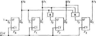
Fig. 2.58 - Synchronous straight binary counter.
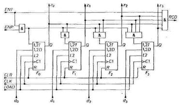
Fig. 2.59 - Practical implementation of integrated synchronous counters.
ENT = Enable T ENP = Enable P
CLR = Clear CLK = Clock
RCO = Ripple Carry Output
Integrated synchronous counters have yet more inputs and outputs whose function and application will be described in further detail with reference to Fig. 2.59. The entire counter can be initialized using the Clear input CLR (Z = 0). It can be set to any number Z = D via the Load input. Whereas the Clear input always operates asynchronously like any Reset input, both synchronous and asynchronous types are available for the load process.
Very large (multiple-bit) counters can be implemented by cascading several 4-bit counter stages. The stages are connected via the ripple carry output RCO and the enable input ENT, which can be used to inhibit the entire counter stage and the carry output. The latter must therefore go to 1 when a count of 1111 is reached and all the lower-order stages likewise produce a carry. For this to occur, the logic operation
RCO = ENT-z0-zt-z2-z3
must be performed in each counter stage. The corresponding output gate is shown in Fig. 2.59.
To cascade the counter stages, it is merely necessary to connect the ENT input of a stage to the RCO output of the next lower-order stage. However, as the delays are cumulative due to the cascaded and operations, multiple-bit counters are subject to a reduction in the maximum possible counting frequency. In this case it is preferable to perform the required and operations in parallel in each counter stage. To do this, the lowest-order stage is omitted from the serial RCO-ENT operation and the enabling of the higher-order stages is controlled in parallel via the ENP inputs. In this way the parallel AND operation can be implemented without external gates, as shown in Fig. 2.60.

Fig, 2.60 - Cascading of synchronous counter stages. CT= Content.
Date: 2015-01-12; view: 1676
| <== previous page | | | next page ==> |
| Asynchronous BCD counter | | | Synchronous BCD counter |