CATEGORIES:
BiologyChemistryConstructionCultureEcologyEconomyElectronicsFinanceGeographyHistoryInformaticsLawMathematicsMechanicsMedicineOtherPedagogyPhilosophyPhysicsPolicyPsychologySociologySportTourism
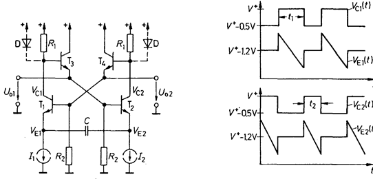
Emitter-coupled multivibrator
Due to the elimination of the storage times, considerably higher frequencies can be achieved with emitter-coupled multivibrators than using saturated transistors. A suitable circuit is shown in Fig.1.14.
To explain how the circuit operates, let us assume that the amplitude of the AC voltages present is small at all points in the circuit, say UPP » 0.5 V. When T1 is OFF, its collector potential is virtually equal to the supply voltage, resulting in an emitter potential of V+ - 1.2 V at T2. Its emitter current is I1 + I2. In order to produce the required amplitude of oscillation at R1, the value R1 = 0.5 V/(I1 + I2) must therefore be selected. This gives us an emitter potential of V+ - 1.1 V at T4 under this operating condition. As long as T1 is OFF, the current from the left current source flows via capacitor C, causing the emitter potential of T1 to fall at a rate of
 .
.
T1 begins to conduct when its emitter potential has fallen to V+ - 1.7 V. The base potential of T2 then falls by 0.5 V, turning the device off, and its collector potential rises to V+. The base potential of T1, rises with it via emitter follower T4, causing the emitter potential of T1 to jump to V+ - 1.2 V. This step is transferred via capacitor C to the emitter of T2, producing a potential increase from V+ - 1.2 V to V+ - 0.7 V across this device.
Date: 2015-01-12; view: 2546
| <== previous page | | | next page ==> |
| Emitter-coupled logic (ECL) | | | Fig. 1.14 - Emitter-coupled multivibrator. Fig. 1.15 - Voltage waveforms. |