CATEGORIES:
BiologyChemistryConstructionCultureEcologyEconomyElectronicsFinanceGeographyHistoryInformaticsLawMathematicsMechanicsMedicineOtherPedagogyPhilosophyPhysicsPolicyPsychologySociologySportTourism
Experiment 1. Measuring the resistance of resistors
Assemble the circuit shown in Fig. 2. 6.
Multimeter readings fill in the table. 2. 5.
The measurement results compare with those shown on fig. 2. 6 the resistance values of the resistors.
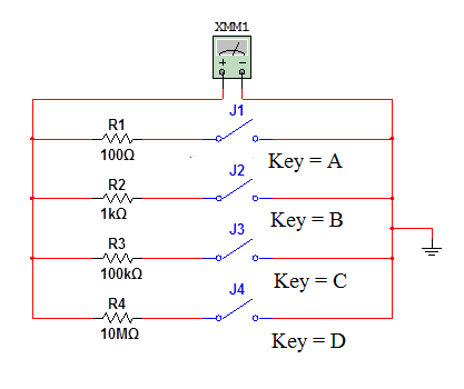
Fig. 2. 6. The scheme for studying the process of measuring the resistance of the resistors
Table 2. 5
The results of measuring the resistance of resistors
| The number of the closed switch | Is the resistance of the resistor |
Experiment 2. Measurement of voltage level
Assemble the circuit shown in fig. 2. 7.
Start the modeling process. Closing alternately sequentially from top to bottom, the switches of assembled circuits, measure the voltage levels of various sources of EMF.
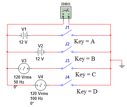
Fig. 2. 7. The scheme to determine of voltage level
Measurement results record in table. 2. 6.
Table 2. 6
Measurement results of voltage levels
| Room closed switch | The measured level voltage | The calculated level voltage |
Compare the results of calculations and measurements.
Questions
1. What are the methods of measurements used in practice?
2. What is the difference between differential and zero measurement methods?
3. That is called absolute, relative, given that the main and additional error?
4. Which system of electrical appliances became widespread?
5. How to expand the measurement range of ammeters and voltmeters?
6. How to determine the ratio of the bypass?
7. How to determine the ratio of the incremental resistor?
8. That's called accuracy class of measuring devices?
9. List the classes of precision measuring instruments.
10. What is called the level of the signal?
Chapter 3. Linear and nonlinear chains DC
______________________________________________
Linear electric DC circuit
Non-linear electric DC circuit
Linear electric DC circuit
Purpose
1. The study of circuits with series and parallel connection of resistors.
2. Checking the equivalence of the replacing of a dipole, consisting of series-connected sources of EMF.
3. Checking the equivalence replacement two-terminal network consisting of parallel connected current sources.
4. Verification of the equivalence of replacing the nonideal current source non-ideal source of EMF.
5. Confirmation of the validity of Ohm's law and Kirchhoff's laws.
Date: 2018-08-27; view: 28913
| <== previous page | | | next page ==> |
| Brief theoretical information | | | Experiment 2. Determination of equivalent resistance of parallel connected resistors |