CATEGORIES:
BiologyChemistryConstructionCultureEcologyEconomyElectronicsFinanceGeographyHistoryInformaticsLawMathematicsMechanicsMedicineOtherPedagogyPhilosophyPhysicsPolicyPsychologySociologySportTourism
Introduction to Digital Computers
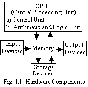
A computer is an electronic device, controlled by instructions stored in memory. (These instructions are called computer programs or software.) Computers perform four basic operations: input, processing, storage, output. These four operations make up the information processing cycle. Any person who uses the computer or results from the computer is considered to be its user. A computer system consists of five primary components (Fig. 1.1).
 Input and Output(I/O)architectures:I/O Devicesenter and output data, programs, commands, and user responses into main memory (main memory is where the computer holds information and data it is currently using). Two most popular are Keyboard and Mouse. The hard- and software Interface is used for coupling units of digital computers.
Random Access Memory (RAM):It stores all data and programs currently being used. (Anything you enter into the keyboard is stored in main memory). It is considered to be a temporary storage because it can only function when the power is on. Once the power is off, main memory (RAM) is erased.
The Central Processing Unit(CPU) contains electronic circuits that cause processing to occur. CPUs are made up of:
a. I/O unit which controls interaction between the CPU and all the other parts of your computer.
b. Arithmetic and Logic Unit (ALU) which handles logic and math functions.
c. Control unit ? tells the other parts of the CPU what to do.
The CPU is contained inside the computer in a chip called a microprocessor. The difference among processors has to do with speed ? how fast can they process instructions. Clock speed is measured in megahertz, abbreviated 'MHz', and gigahertz, abbreviated 'GHz'. For the last 10 years, CPU?s have been measured in Megahertz (MHz ? Millions of cycles per second). Newer CPU?s on the market today can be measured in Gigahertz (GHz ? Billions of cycles per second).
We shall now turn our attention to the organization and operation of the different building blocks that comprise a computer system. In its simplest form, a computer system has one unit that executes program instructions. This unit communicates with, and often controls the operation of, other subsystems within the computer. Because of the central role of such a unit, it is known as a central processing unit, or CPU. In many computers, a subsystem within the computer, such as an input unit or a mass storage device, may incorporate a processing unit of its own. Such a processing unit, while being central to its own subsystem, is clearly not "central" to the computer system as a whole. However, the principles involved in the design and operation of a CPU are independent on its position in a computer system. We will deal with the organization of the hardware, which enables a CPU to perform its main function: to fetch and execute instructions.
Fundamental Concepts.The solution algorithm for any problem consists of a number of steps that should be carried out in a specific sequence. To implement such an algorithm on a computer, these steps are broken down into a number of smaller steps, where each of smaller steps represents one machine instruction. The resulting sequence of instructions is a machine language program representing the algorithm in question. The same general approach is used to enable the computer to perform the functions specified by individual machine instructions. That is, each of these instructions is executed by carrying out a sequence of more rudimentary operations.
The instructions constituting a program to be executed by a computer are loaded in sequential locations in its main memory. To execute this program, the CPU fetches one instruction at a time and performs the functions specified. Instructions are fetched from successive memory locations until the execution of a branch or jump instruction. The CPU keeps track of the address of the memory location where the next instruction is located through the use of a dedicated CPU register, referred to as the program counter (PC). After fetching an instruction, the contents of the PC are updated to point at the next instruction in sequence [2], [13], [38], [42], [47], [48], [55], [59], [60], [61], [62].
Let us assume, for simplicity, that each instruction occupies one memory word. Therefore, execution of one instruction requires the following three steps to be performed by the CPU:
1. Fetch the contents of the memory location pointed at by the PC.
The contents of this location are interpreted as an instruction to be executed. Hence, they are stored in the instruction register (IR). Symbolically, this can be written as IR ← [[PC]].
2. Increment the contents of the PC by 1. PC ← [PC] + 1.
3. Carry out the actions specified by the instruction stored in the IR.
Note that in cases where an instruction occupies more than one word, steps 1 and 2 can be repeated as many times as necessary to fetch the complete instruction. These two steps are usually referred to as the fetch phase, while step 3 constitutes the execution phase.
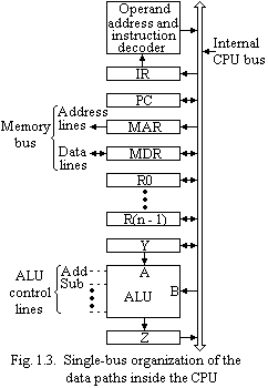
Before proceeding to study the above operations in detail, we shall pause briefly to examine the structure of the main data paths inside the CPU. Most of the building blocks of the CPU are introduced in Fig. 1.2, which shows how the connection between the main memory and the processor can be made.
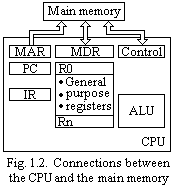 The processor contains arithmetic and logic circuitry as the main processing elements. It also contains a number of registers used for temporary storage of data. There are two registers that facilitate communication with the main memory. These are the memory address register (MAR) and the memory data register (MDR). As the name implies, the MAR is used to hold the address of the location to or from which. The blocks of Fig. 1.2 can be organized and interconnected in a variety of ways. One such organization is shown in Fig. 1.3. In this case, the arithmetic and logic unit (ALU) and all CPU registers are connected via a single common bus. This bus, of course, is internal to the CPU, and should not be confused with the external bus, or buses, connecting the CPU to the memory and I/O devices. The external memory bus is shown in Fig. 1.3 connected to the CPU via the memory data and address registers MDR and MAR. The number and function of registers R0 to R(n ? 1) vary considerably from one machine to another. The programmer may provide them for general-purpose use. Alternatively, some of them may be dedicated as special-purpose registers, such as index registers or stack pointers.
Two registers in Fig. 1.3, namely, Y and Z, have not been mentioned before. These registers are transparent to the programmer. That is, the programmer need not be concerned with their existence, since they are never referenced directly by any instruction. They are used only by the CPU for temporary storage during execution of some instructions.
|
However, they are never used for storing data generated by one instruction for later use by another instruction. The means by which registers Y and Z, as well as other components in Fig. 1.3, participate in instruction execution will become apparent from the ensuing discussion.
With few exceptions, most of the operations in steps 1 to 3 mentioned earlier can be carried out by performing one or more of the following functions in some prespecified sequence:
1. Fetch the contents of a given memory location and load them into a CPU register.
2. Store a word of data from a CPU register into a given memory location.
3. Transfer a word of data from one CPU register to another or to the ALU.
4. Perform an arithmetic or logic operation, and store the result in a CPU register.
Date: 2016-06-12; view: 342
| <== previous page | | | next page ==> |
| Tendrá que volver | | | The Computer Work Stages Implementation Sequence |