CATEGORIES:
BiologyChemistryConstructionCultureEcologyEconomyElectronicsFinanceGeographyHistoryInformaticsLawMathematicsMechanicsMedicineOtherPedagogyPhilosophyPhysicsPolicyPsychologySociologySportTourism
The basic theoretical information
Laboratory work #3
INVESTIGATION OF REMOTE-INDICATING ELECTRICAL
AVIATION TACHOMETERS
Work objectives: learn the principle of operation, structure, properties and exploitation features of remote-indicating electrical aviation tachometers, get the basic technical characteristics, analyze influencing factors, clarify the reasons of errors and find out, how to decrease its amount.
MAIN TASK
1. Learn the principle of operation and structure of tachometer and laboratory plant.
2. Verify one measurement channel of tachometer (pickup - one indicator) and draw graphs that indicate an absolute error and variation dependency on its readings.
3. Verify pickup - two indicators channel draw graphs that indicate an absolute error and variation dependency on its readings.
4. Clarify the dependencies of tachometer readings, frequency values, linear voltages, current used by one measurement channel on pickup shaft rotation frequency. Draw graphs of gotten dependencies and calculate apparent pickup power.
5. Discover the influence of wires resistance changes on tachometer readings.
The basic theoretical information
One of the basic parameters, which permit to determine engine traction, is aviation engine shaft rotation frequency. Tachometers are the devices, used to measure this parameter.
Drag-type (eddy current) electrical tachometers become widely used because of their simplicity and reliability. The measurement range of rotation frequency of these devices is rather wide: 4,00 – 4000 revolutions per minute (rpm) of reciprocator and 1000 – 20000 rpm of turboprop engine. There is dependence between the number of revolutions per minute (rpm) n and shaft rotation frequency (angular rotation velocity)  (radians per second):
 ,
,
where  , (F – frequency in Hz).

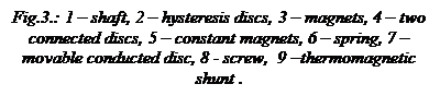
Fig.1.:1 – gauge of tachometer, 2 – stator winding, 3 - hysteresis discs, 4 – 2 cross-formed constant magnets, 5 - embedded constant magnets, 6 – thermomagnetic shunt, 7 - moveable conducted disc, 8 – spring, 9 – damping disc, 10 - damping magnets, 11 – pointer.
Like any other measurement device, tachometer consists of three basic components: gauge (fig.1, 1andfig.2), converter of the gauge output signal and indicating device. Gauge is used to convert shaft rotation frequency into electric signal  , which frequency is linearly connected with (the number of revolutions n).
Tachometer gauge (fig.2) is a synchronous AC-generator with variable frequency. Rotor of the gauge is a bipolar or fourpolar magnet, connected with an aviation engine drive shaft by tang 1 – a long thin roller, inserted in an empty bush 3.
 Generator rotor is rotating inside stator coils 5, placed into twelve slots of set 9, made from transformer iron plates. Plates with winding are inside the case, which consists of back 6 and front 8 halves, tided up with screw-bolts 7. On the front half of the case 8 there is a coupling nut 10 – a binding of a generator to an aviation engine.
 Generator stator windings are connected with stator windings 2 (fig.1) of a synchronous engine. Three-phase current, which frequency is proportional to the engine rotor rotation frequency, goes from generator to stator windings of synchronous engine and excites rotating magnetic field in it. Rotor of synchronous engine consists of 2 cross-formed constant magnets (fig.1, 4 and fig.3, 3) and a set of hysteresis discs (fig.1, 3 and fig.3, 2). Constant magnets are connected with shaft (1 in fig.3) by spring. Such construction of the rotor allows decreasing its mass greatly and also it permits to increase rotating moment of the rotor along the whole velocity range – from start to synchronous rotation speed.
 The rotating magnetic field, excited in the synchronous engine stator windings, magnetize hysteresis discs (made of ferromagnetic alloy with large coercive force). Magnetic field of the discs follows poles of the rotating magnetic field, but due to large hysteresis in the material poles of the discs remain behind poles of the stator field to certain angle. As a result, the moment of rotation appears which rotates rotor of the synchronous engine.
 If rotor rotates with frequency, close to synchronous, permanent magnets 3 (fig.3) have time to interact with stator field, lock in synchronism and, turning the spring round, begin to take full load. In this case the main rotating moment is created as a result of interaction of the field of permanent magnets with rotating stator field, and hysteresis discs create just little additional moment.
If some sudden change in rotation frequency of the engine shaft happens, then rotor of the synchronous engine can break the synchronous rotation. In this case hysteresis discs help moving system to lock in synchronism again.
A sensitive element of tachometer consists of two connected discs 4 (fig.3) with embedded constant magnets (fig. 1, 5 and fig.3, 5) and thermomagnetic shunt (fig. 1, 6 and fig.3, 9) on them. Also there is a moveable conducted disc 7 (fig.3) in a magnetic field of the magnets 5. Discs 4 are situated on the same axis with engine rotor and disc 7 is mounted at the axis of the indicator pointers. Damper disc and one end of counteractive spring are strengthened to this axis.
During the rotation of discs 4 (fig.3) with magnets 5, the eddy currents appear inside the disc 7, creating their electromagnetic field. As a result of interaction between the cores magnetic fields and eddy currents, the moment appears, trying to rotate the disc 7 to the direction of tachometric unit rotation. Spiral spring 6 prevents this rotation.
To decrease dynamic errors during the transient processes, the second eddy current unit is used as a damper. Disc 9 (fig.1) is placed on the axis of pointer 11 and the disc with damping magnets 10 is mounted rigidly to device’s case. At significant oscillation of the rotation frequency in moving system eddy currents appear in the damping disc. These currents interact with magnetic field of constant magnets 10, leading to damping of oscillations in moveable indicator system with pointer.
Kinematics of dual indicator with sensitive elements is shown on fig.4.

Fig.4. Kinematics of the dual indicator:
1, 4, 5, 6 – gearing, 2,3 – pointers, 7,8 – eddy current units.
This scheme differs from the scheme of one-pointer indicator in presence of specific gearing 1, 4, 6, and 5. By means of this gearing the two pointers 2 and 3 move from their drag-type units 7 and 8 each. Friction in the gearing reduces pointers oscillations, appearing at transient processes. That is why in two-pointer (dual) indicator on fig.5, b, the drag-type damping unit is not used (in contrast to the one-pointer indicator fig.5, a).
|
|
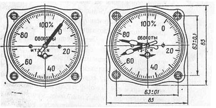
Fig.5
The main errors appear in tachometer as a result of change of moving element electric resistance, induction in the air-gap, characteristics of constant magnets, and the construction parameters of sensitive element, linear dimensions of counteractive spring and absolute value of its material resilience because of the environment temperature. The moving element is made with small temperature coefficient. Other temperature changes are compensated in the device by means of temperature shunt 6 (fig.1), fastened on the constant magnets 5. The main instrumental errors of tachometer are determined by friction in bearings of moving units and scale calibration errors, which are equal to 1%. Tachometer ITE - 2 (electric tachometric instrument) differs from ITE – 1 by the fact, that it has two pickups such as PTE (electric tachometric pickup). These pickups are connected with their engine shaft and appropriate sensitive element each. Both measuring units are assembled in one case and have combined axis of pointers indicator (fig.5, b). As the gear couples are used for transmission of moving element rotation angle to the pointer axis, and there is friction in these gear couples, promoting quick attenuation of the moving systems, so there are no dampers in measuring units of the concerned indicators.
The most typical malfunctions in tachometer operation are demagnetization of measuring unit magnets and faulty phase connection of the pickup and indicator.
Date: 2016-03-03; view: 1514
| <== previous page | | | next page ==> |
| Higher and Further Education in the United Kingdom. | | | Type 4 Decision tree |