CATEGORIES:
BiologyChemistryConstructionCultureEcologyEconomyElectronicsFinanceGeographyHistoryInformaticsLawMathematicsMechanicsMedicineOtherPedagogyPhilosophyPhysicsPolicyPsychologySociologySportTourism
Eliminating clutter
History
As early as 1886, German physicist Heinrich Hertz showed that radio waves could be reflected from solid objects. In 1895, Alexander Popov, a physics instructor at the Imperial Russian Navy school in Kronstadt, developed an apparatus using a coherer tube for detecting distant lightning strikes. The next year, he added a spark-gap transmitter. In 1897, while testing this equipment for communicating between two ships in the Baltic Sea, he took note of an interference beat caused by the passage of a third vessel. In his report, Popov wrote that this phenomenon might be used for detecting objects, but he did nothing more with this observation.
The German inventor Christian Hülsmeyer was the first to use radio waves to detect "the presence of distant metallic objects". In 1904 he demonstrated the feasibility of detecting a ship in dense fog, but not its distance from the transmitter. He obtained a patent for his detection device in April 1904 and later a patent for a related amendment for estimating the distance to the ship. He also got a British patent on September 23, 1904 for a full system, that he called a telemobiloscope.
In August 1917 Nikola Tesla outlined a concept for primitive radar-like units. He stated,
...by their [standing electromagnetic waves] use we may produce at will, from a sending station, an electrical effect in any particular region of the globe; [with which] we may determine the relative position or course of a moving object, such as a vessel at sea, the distance traversed by the same, or its speed.
In 1934 the Frenchman Émile Girardeau stated he was building an obstacle-locating radio apparatus "conceived according to the principles stated by Tesla" and obtained a patent for a working system, a part of which was installed on the Normandie liner in 1935.
During the same time, the Soviet military engineer P.K.Oschepkov, in collaboration with Leningrad Electrophysical Institute, produced an experimental apparatus, RAPID, capable of detecting an aircraft within 3 km of a receiver. The French and Soviet systems, however, had continuous-wave operation and could not give the full performance that was ultimately at the center of modern radar.
In April 1940, Popular Science showed an example of a radar unit using the Watson-Watt patent in an article on air defence, but not knowing that the U.S. Army and U.S. Navy were working on radars with the same principle, stated under the illustration, "This is not U.S. Army equipment." Also, in late 1941 Popular Mechanics had an article in which a U.S. scientist speculated about the British early warning system on the English east coast and came close to what it was and how it worked. Alfred Lee Loomis organized the Radiation Laboratory at Cambridge, Massachusetts which developed the technology in the years 1941-45. Later, in 1943, Page greatly improved radar with the monopulse technique that was used for many years in most radar applications.
Principles
Primary (passive) radar is mainly used for target detection, lighting up their electromagnetic wave, and then taking the reflection (echo) of the wave from the target. As the velocity of electromagnetic waves is constant (speed of light), it is possible to determine the distance to the target, based on the measurement of various parameters of signal propagation.
At the heart of the radar device is based on three components: a transmitter, an antenna and a receiver.
Transmitter is a source of high power electromagnetic signal. It can be a powerful pulse generator. For pulsed radar centimeter - usually a magnetron or a pulse generator operating under the scheme: master oscillator - power amplifier using a generator often traveling wave tube, and for the radar meter band often use triode tube. Depending on the design, the transmitter operates in either a pulsed mode, forming a repetitive short powerful electromagnetic pulses, or emits continuous electromagnetic signal.
Focuses antenna transmitter signal and beamforming, and reception of the reflected signal from the target and the transmission of the signal to the receiver. Depending on the implementation of the reception of the reflected signal can be either the same antenna or the other, which sometimes can be located at a considerable distance from the transmitter. If the sending and receiving combined in a single antenna, the two actions are performed alternately, to a strong signal leaking from the transmission of the transmitter to the receiver is not blinded receiver weak echo, before the receiver is placed a special device that closes the entrance to the receiver at the time of emission of the signal.
Receiver performs amplification and processing of the received signal. In the simplest case, the resulting signal is fed to the cathode ray tube (screen), which shows an image, synchronized with the movement of the antenna.
Various radar based on different methods of measuring the reflected signal:
1) Frequency range measurement method based on the use of frequency modulation emitted continuous signals. In this method, for the period emitted frequency varies linearly from f1 to f2. The reflected signal will be modulated linearly in time, prior to this time delay. Thus frequency of the reflected signal received by the radar will be proportional to time-dependent. The time delay is determined by the abrupt change in the frequency difference signal.
Advantages:
-can measure very small range;
-uses a low-power transmitter;
Disadvantages:
-requires the use of two antennas;
-degradation in receiver sensitivity due to leakage through the antenna to the receiving channel transmitter radiation subjected to random variations;
-high linearity requirements frequency change;
2) Phase (coherent) approach radar is based on the isolation and analysis of the phase difference of the reflected signals sent and that is due to the Doppler effect, when the signal is reflected from a moving object. In this case, the sending device can operate continuously or in pulsed mode. The main advantage of this method is that it "allows us to observe only the moving objects, which eliminates interference from fixed objects located between the receiving equipment and purpose, or for her."
Since in this case uses very high frequency, the unambiguous measurement range range of the order of several meters. In practice, therefore using more complex schemes in which there is two or more frequencies.
Advantages:
-low-power radiation, as generated sustained oscillations;
-accuracy is independent of the Doppler shift of reflection;
-fairly simple device;
Disadvantages:
-lack of resolution in range;
-degradation in receiver sensitivity due to the penetration of the antenna to the receiving channel transmitter radiation subjected to random variations;
3) Pulse Method. Modern radar tracking built as pulsed radar. Pulse radar transmits the signal emitted only for a very brief time, a short pulse (usually about a microsecond), and then goes into receive mode and listens to the echo reflected from the target, while the emitted pulse propagates in space.
Since the momentum goes away from the radar at a constant speed, the time elapsed since the sending pulse and before the reception of the echo response - there is a direct dependence of the distance to the target. The next pulse can be sent only after some time, namely, after the momentum will come back (depending on the detection range of the radar transmitter power, antenna gain, receiver sensitivity). If a pulse is sent before the echo from the previous pulse distant target can be confused with the second pulse echo from the nearby target.
The time interval between pulses is called interval repetition, its inverse value - an important parameter, which is called the pulse repetition frequency (PRF). Low frequency radars see far ahead, usually have a repeat interval of a few hundred pulses per second. The pulse repetition rate is one of the distinguishing features by which possibly remote definition of the model radar.
Advantages:
-the possibility of building a radar antenna;
-simple display device;
-ease ranging several purposes;
-easy emitted pulses lasting a very short time [pic], and received signals;
Disadvantages:
-the need to use high pulse power transmitter;
-inability to measure small distances;
-large dead zone;
Eliminating clutter
One of the main problems of pulse radar is getting rid of the signal reflected from fixed objects: the Earth's surface, high hills, etc. If for example, the aircraft is on the background of a high hill, the reflected signal from this hill completely block the signal from the aircraft. For ground-based radar is affected when working with low-flying objects. For airborne radar pulse is reflected in the fact that the reflection from the Earth's surface obscures all the objects located below the aircraft with radar.
Methods used to prevent hindrance, somehow, the Doppler effect (the frequency of the wave reflected from the approaching object increases by passing the object - decreases).
The simplest radar that can detect a target in the noise - radar with moving target indication (MTI) - pulsed radar, which compares the reflections of one or two or more pulse repetition intervals. Any target that is moving relative to the radar, produces a change in the signal parameters (step sequential MTI), while noise remains unchanged. Eliminating interference occurs by subtracting the reflections of two consecutive intervals. In practice, interference avoidance can be achieved in special devices - by periodic compensators or algorithms in the software.
Another way of getting rid of noise is implemented in a pulse-Doppler radar, which use much more complicated process than the MTI radar.
An important property of a pulse-Doppler radar - is a coherent signal. This means that the signals sent and reflection must have a certain phase relationship.
Pulse-Doppler radar is usually considered better MTI radar detection of low-flying targets at multiple interference land, it - the preferred technique used in modern fighter aircraft to intercept / fire control.
"Secondary radar" is used for the identification of aviation aircraft. The main feature - the use of an active defendant in airplanes.
The principle of operation of the secondary radar is slightly different from the principle of primary radar. At the heart device Secondary radar are components: a transmitter, antenna, generator azimuth marks, receiver, signal processor, display and aircraft defendant with an antenna.
Transmitter - used to query the radiation pulses at a frequency of the antenna 1030 MHz.
Antenna - used for transmitting and receiving the reflected signal. By the standards of ICAO for the secondary radar antenna radiates at a frequency of 1030 MHz and receives at a frequency of 1090 MHz.
Generators azimuth labels - are used to generate the azimuth marks (Azimuth Change Pulse or ACP) and the generation of labels North (Azimuth Reference Pulse or ARP). Per revolution generated radar antenna azimuth 4096 small labels (for older systems) or 16384 small azimuthal labels (for new systems, they are called enhanced small azimuth marks (Improved Azimuth Change pulse or IACP), and the same label of the North. Label comes north the generator azimuth marks in this position the antenna when it is directed to the north, and small labels are used for the azimuthal angle of rotation of the reference antenna.
Receiver - is to receive pulses at a frequency of 1090 MHz.
Signal processor - used for processing the signals.
Indicator is used to display the processed information.
Aircraft responder with antenna - used to transfer the pulse signal containing additional information back towards the radar signal when receiving the request.
The principle of operation of the secondary radar is to use the power of aircraft to locate the defendant aircraft. Radar illuminates the surrounding space request was on the frequency P1 and P3, and P2 suppression pulse at a frequency of 1030 MHz. Equipped defendants aircraft within range of the beam request when request was received, if the condition is valid P1, P3> P2 meet the demands of the radar, a series of coded pulses at a frequency of 1090 MHz, which provide additional information about the number of sides, height and so on . The answer depends on the aircraft defendant to request the radar, and the mode of inquiry determined by the interval of time between the request was P1 and P3, for example, in a query mode (mode A) the time interval between the request was station P1 and P3 is 8 microseconds and upon receipt of such a request the respondent aircraft codes in pulses answer your number board.
In Query Mode C (mode C) the time between request was station is 21 microseconds and on receipt of the request of the defendant aircraft codes in pulses answer your height. RLS also can send a request in a mixed mode, such as Mode A, Mode S, Mode A and Mode C aircraft azimuth angle is determined by the antenna, which in turn is determined by counting the small azimuthal tags.
Range is determined by the delay came the answer. If the aircraft is in range of the side lobes, but not the main beam, or is behind the antenna, the defendant aircraft when requested by a radar receives at its input the condition that the pulses P1, P3 <P2, that is, more pulses pulse suppression request . In this case, the defendant is locked and does not respond to the request.
The received signal is processed by the defendant radar receiver, then goes to the signal processor, which carries out signal processing and delivery of information to the end user and (or) on the pilot light.
Pros secondary radar:
-higher accuracy;
-more information about the aircraft (number of sides, height);
-small compared with the primary radar radiation power;
-long range detection.
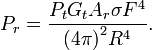
Radar equation
The power Pr returning to the receiving antenna is given by the equation:

where
-Pt = transmitter power
-Gt = gain of the transmitting antenna
-Ar = effective aperture (area) of the receiving antenna
-σ = radar cross section, or scattering coefficient, of the target
-F = pattern propagation factor
-Rt = distance from the transmitter to the target
-Rr = distance from the target to the receiver.
In the common case where the transmitter and the receiver are at the same location, Rt = Rr and the term Rt² Rr² can be replaced by R4, where R is the range. This yields:
Date: 2016-01-14; view: 1519
| <== previous page | | | next page ==> |
| Internal Input Monitoring | | | Keeping Us in Line: Train Tracks |