CATEGORIES:
BiologyChemistryConstructionCultureEcologyEconomyElectronicsFinanceGeographyHistoryInformaticsLawMathematicsMechanicsMedicineOtherPedagogyPhilosophyPhysicsPolicyPsychologySociologySportTourism
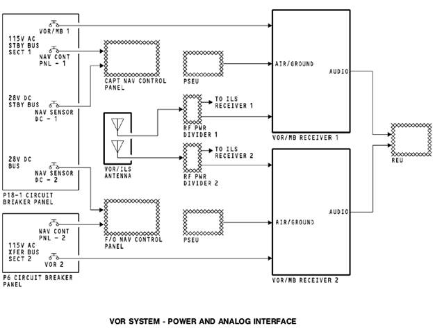
VOR SYSTEM - POWER AND ANALOG INTERFACE
General
These are the components that have power and analog interface with the VOR system:
· Circuit breakers
· VOR antenna
· Navigation control panels
· Card files
· Remote electronics unit.
Circuit breakers
The VOR circuit breakers supply 115v ac power for receiver operation. VOR/MB receiver 1 gets power from the ac standby bus, section 1 and VOR/MB receiver 2 gets power from the ac transfer bus 2, section 2.
The NAV control panel circuit breakers supply 115v ac for control panel operation. The captain control panel gets power from the ac standby bus and the first officer control panel gets power from the ac transfer bus 2.
The NAV control panels receive 28v dc for control panel monitor operation and for the ILS 28v dc ILS tuned output when you tune an ILS frequency. The captain control panel receives 28v dc from the 28v dc standby bus, NAV sensor DC-1 circuit breaker. The first officer control panel receives 28v dc from the 28v dc bus 2, NAV sensor DC-2 circuit breaker.
VOR/ILS Antenna
The VOR/ILS antenna sends RF signals through the RF power divider 1 and RF power divider 2, to the VOR/MB receivers.
PSEU
The VOR/MB receivers get air/ground inputs from the proximity switch electronics unit (PSEU). The receiver uses the inputs to set the flight leg count for internal memory, and also inhibit test in the air.
REU
The remote electronics unit (REU) receives morse code station identifier signals and station audio from the VOR/MB receivers and supplies them to the flight interphone speakers and headsets.
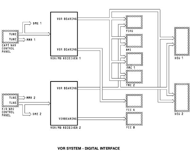
VOR SYSTEM - DIGITAL INTERFACE
General
All digital interfaces are on ARINC 429 data buses. These are the components that have digital interface with the VOR/MB receivers:
· Captain and first officer NAV control panel
· Flight data acquisition unit (FDAU)
· Radio magnetic indicator (RMI)
· Flight management computers (FMC 1, FMC 2)
· Flight control computer (FCC) A
· FCC B
· Display electronics unit (DEU) 1
· DEU 2.
NAV Control Panel
The captain and first officer NAV control panels send manual tune and test command inputs to the VOR/MB receivers. The NAV control panels send tune inputs and test commands out on two data buses. One data bus goes to the multi mode receivers (MMR) and one data bus goes to both the VOR receiver and the DME interrogators.
VOR/MB Output
The VOR/MB receivers each have two output buses. One output bus from each receiver goes to the on-side FCC. VOR/MB receiver 1 supplies VOR data and status to FCC A. VOR/MB receiver 2 supplies VOR data and status to FCC B. The FCCs use the data for the autopilot VOR mode of operation. The other output bus of each receiver sends VOR data and status to these components:
· FDAU for data to record by the digital flight data recorder
· RMI for bearing pointer displays
· FMC for position update calculations
· FMC 1 and FMC 2 for position update calculations
· DEUs for VOR displays.
VOR SYSTEM - VOR/MB RECEIVER
General
The VOR/marker beacon (VOR/MB) receiver contains the VOR receiver function and the marker beacon function. The VOR/MB receiver supplies magnetic bearing data from a VOR ground station.
Description
The VOR/MB receiver ia a standard ARINC 3 MCU unit with dimensions approximately 3.74”x 7.87”x 14.76”. The receiver weighs 9 pounds and uses 115v ac 400 Hz power for operation.
Date: 2015-12-24; view: 2133
| <== previous page | | | next page ==> |
| VOR SYSTEM - FLIGHT COMPARTMENT COMPONENT LOCATION | | | Test and Indication |