CATEGORIES:
BiologyChemistryConstructionCultureEcologyEconomyElectronicsFinanceGeographyHistoryInformaticsLawMathematicsMechanicsMedicineOtherPedagogyPhilosophyPhysicsPolicyPsychologySociologySportTourism
Structures of data: primitive types, massifs, lines. Block diagrams as graphic realization of algorithms.
On case of the block and circuit description the algorithm is figured by the geometrical figures (units) connected on control of lines (the flow directions) with arrows. In units the sequence of actions registers.
This method in comparison with other methods of record of algorithm has a row of advantages. It is most evident: each operation of calculating process is figured by separate geometrical figure. Besides, the graphics image of algorithm demonstrates ramifying of solutions of the task depending on different conditions, repetition of separate stages of calculating process and other details.
Design of programs shall correspond to certain requirements.
Operations of data handling and information media are figured on the diagram by the appropriate units. The most part of units on creation is conditional inscribed in a rectangle with the sides a and b. The minimum value and is equal 10 mm, the increase and is made on the number multiple of 5 mm. B=1,5 size of mm. For separate units the ratio between a and b, equal 1:2 is allowed. Within one diagram it is recommended to figure units of the identical sizes. All units are numbered. Types and assignment of main units are given in table 5.1.
The lines connecting units and specifying sequence of communications in between, shall be carried out parallel to frame lines. The arrow at the end of the line cannot be put, if the line is directed from left to right or from top to down. The unit can include some lines, which are the unit can be the successor of any number of units. Only one line can quit the unit (except logical). The logic block can have one of two units, and of it as continuation there are two lines. If on the diagram merge of lines takes place, the place of intersection is selected with a point. In a case when one line approaches to another and their merge is explicitly expressed, the point can be not put. The diagram of algorithm should be executed as a unit, however it is in case of need allowed to tear off the lines connecting units.
If in case of a line breakaway continuation of the diagram is on the same leaf, on one and other end of the line the special character a connector – a circle in diameter of 0,5 mm is figured. In conjugate circles the same identifier is specified. As the identifier the sequence number of the unit to which the connecting line is directed is, as a rule, used. If the diagram occupies more than one leaf, in case of a rupture of the line instead of a circle the inter page connector is used. In each connector the address – from where and where the connecting line is directed is specified. The address registers in two lines: in the first leaf number, in the second – sequence number of the unit is specified.
Table 5.1 – Table of main units:
| 1.process | 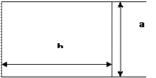
|
| 2.predetermined process (subprogram) | 
|
 3. flowlines
| |
 4. beginning - end
| |
 5. condition
| |
| 6. input-output | 
|
| 7. modification | 
|
| 8. comments | 
|
| 9. inside - page | 
|
| 10. inter page connector | 
|
Date: 2015-12-24; view: 3407
| <== previous page | | | next page ==> |
| Strategy of realization of algorithms. | | | Analysis of algorithms |