CATEGORIES:
BiologyChemistryConstructionCultureEcologyEconomyElectronicsFinanceGeographyHistoryInformaticsLawMathematicsMechanicsMedicineOtherPedagogyPhilosophyPhysicsPolicyPsychologySociologySportTourism
Working with Joint Primitives
A joint primitive places a restriction on relative motion, such as restricting one part to always move parallel to another part. The joint primitives do not have physical counterparts as the idealized joints do. You can, however, combine joint primitives to define a complex constraint that cannot be modeled using the idealized joints.
Table 2.5 lists the different types of joint primitives that are available in ADAMS/View.
Table1 2.5 Joint Primitives in ADAMS/View
| Icon | The primitive | An example | Constrains the following | DOF | |
| T | R | ||||

| Inline | 
| One part so that it can only move along a straight line defined on a second part. The location of the inline joint on the first part must remain on the z-axis of the second part. | ||

| Inplane | 
| One part so that it can only move in a plane of a second part. The origin of the inplane joint on the first part must remain in the xy plane of the second part. | ||

| Orientation | 
| The coordinate system of one part so that it cannot rotate with respect to a second part. The axes of the coordinate systems must maintain the same orientation. The location of the origins of the coordinate systems does not matter. | ||

| Parallel axes | 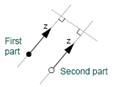
| The z-axis of the coordinate system of one part so that it remains parallel to the z-axis of the coordinate system of a second part. The coordinate system of the first part can only rotate about one axis with respect to the coordinate system of the second part. | ||

| Perpendicular axes | 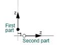
| The coordinate system of one part so that it remains perpendicular to the z-axis of a second part. The coordinate system of the first part can rotate about two axes with respect to the second part. |
To create a joint primitive:
1) From the Jointpalette, select the joint primitive tool representing the joint that you want to create.
2) In the settings container, specify the following:
How you want the joint connected to parts. You can select the following:
Ÿ 1 Location - Bodies implicit- Lets you select the location of the joint and have ADAMS/View determine the two parts that should be connected. ADAMS/View selects the parts closest to the joint location. If there is only one part near the joint, ADAMS/View connects the joint to that part and ground.
Ÿ 2 Bodies - 1 Location- Lets you explicitly select the two parts to be connected by the joint and the location of the joint.
Ÿ 2 Bodies - 2 Locations- Lets you explicitly select the two parts to be connected by the joint and the location of the joint on each part. You should use this option if you are working in exploded view.
How you want the joint oriented. You can select:
Ÿ Normal to Grid- Lets you orient the joint along the current working grid, if it is displayed, or normal to the screen.
Ÿ Pick Geometry Feature- Lets you orient the joint along a direction vector on a feature in your model, such as the face of a part.
3) If you selected to explicitly select the parts to be connected, select each part in your model using the left mouse button.
4) Place the cursor where you want the joint to be located, and click the left mouse button. If you selected to specify its location on each part, place the cursor on the second location and click the left mouse button.
5) If you selected to orient the joint along a direction vector on a feature, move the cursor around in your model to display an arrow representing the direction along a feature where you want the joint oriented. When the direction vector represents the correct orientation, click the left mouse button.
ADAMS/View creates the joint at the specified location.
Date: 2015-12-18; view: 6362
| <== previous page | | | next page ==> |
| Working with Idealized Joints | | | Working with Higher-Pair Constraints |