CATEGORIES:
BiologyChemistryConstructionCultureEcologyEconomyElectronicsFinanceGeographyHistoryInformaticsLawMathematicsMechanicsMedicineOtherPedagogyPhilosophyPhysicsPolicyPsychologySociologySportTourism
In-flight entertainment systems.
IFE is becoming big business and a factor in determining who flies with whom. (It is well known that if the IFE fails in flight there will be more passenger complaints than if there is an engine failure.) It is also a cause for concern amongst designers as electrical cables etc are being pushed to their limits for current carrying capacity.
The systems fitted to aircraft can vary considerably depending on the operator, whether the aircraft is short haul or long haul, whether it is a budget carrier and what class of seating is being considered - and the manufacturer of the IFE equipment. An IFE system can include:
* Power supplies - to various LRUs (Line Replacement Units).
* Power supplies to equipment brought on by passengers (eg laptops)
* Cables - power and signal.
* Tape and cd audio signal reproducers. Housed in a locker in the passenger cabin or a special cabinet or housed in the aircraft's E & E bay. Locations may need special provision for cooling (open mesh sides, cooling fans etc) as the heat generated can be considerable.
* Tape and cd audio and visual signal (video and cd) reproducers. Also housed in a passenger cabin locker or cabinet or E & E bay.
* Monitor television sets (for cabin staff use - in a cabin locker).
* Speakers in the ceiling decor panels, arm-rests etc.
* Projectors (usually the three primary colour gun type). Housed in fixed or retractable units in the ceiling.
* Projection screens. Stowed during take-off and landing.
* Television sets. Located at various positions along the cabin.
* Flat screen displays. Located in the cabin ceiling (retractable or fixed) or in the cabin decor or as part of each seat.
* Multiplex (MUX) and de-multiplex (DEMUX) units.
* Games and Passenger Control Units (PCU) located at each seat.
* Telephone - often part of the PCU.
* Various electronic boxes, Digital to Analogue (D/A) and Analogue to Digital (A/D) converters, Seat Electronics Boxes (SEBs) etc.
* External cameras.
* Connections to flight data computers.
* Reading lamp control. Attendant call button etc.
* Storage for cds, videos etc.
Seat Controls
These will vary depending on the system fitted to the aircraft. For a simple "back ground music system" the seats will not normally have any controls. For a more sophisticated system each seat may be fitted with:
· A flat screen - in the back, for the seat behind, or housed in the arm rest, or positioned in the decor panelling (for some first class seats).
· A Passenger Control Unit (PCU) which may be portable, attached to the seat by a cable, or it may be fixed to the seat arm rest. This is used to control the volume of the sound, select channels, used as a telephone etc.
· A games control unit - which may be part of the PCU. For selecting and the control of various computer games.
 Fig. 2 TELEPHONE/PCU HANDSET
|
· A telephone with provision to accept credit card details either bousing the number keys or using the swipe facility. Again this may be part of the (portable) PCU.
Except for background music systems only the seat will have provision to insert a head-phone set. For some of the (cheaper) systems the sound signal is to a speaker in the arm rest and the sound is transmitted to the passenger's ears by flexible air tubes which are plugged into the side of the arm rest. For other systems the speakers are part of the head-phones and these are plugged into the system via a head-phone jack (socket) on the side of the arm-rest.

|
Fig. 1 UNFOLDING AN ARM-REST MOUNTED SCREEN

Head-phones are supplied to each passenger after boarding and returned to the cabin staff before landing. They are re-used after inspection and the changing of the ear contact pads. Figure 1 shows a typical arm rest mounted screen and figure 2 shows a typical pull-out PCU/telephone.
To get the audio signals (and visual signals if each seat is fitted with its own screen) to the seat, and passenger signals from the seat, cables are laid in the seat tracks. These go to SEBs located under the seat and are connected at the other end to junction boxes which are then connected to MUX units. The cables are laid within the tracks and covered by a plastic track cover (figure 3).
Note. In figure 3 the seat has an electronics unit, sometimes called an SEB, and video units as well.
Seat fixing to the floor is by means of special clamps that lock the seat to the seat tracks. Each track is basically a hollow aluminium alloy extrusion with a series of connected holes at about 1" (25.4mm) pitch. The seat locating lugs are slotted into the track and moved forward about 0.5" (12.5mm) and locked into position by a special lock mechanism.
This means that the seat assembly can be readily replaced or re-position forwards or backwards by maintenance staff to suit different cabin configurations. During this process it is most important that all cables routed to and from the seat are checked for correct attachment to the seat and correct lay within the seat track, and that cables are clean, dry, undamaged and not trapped in any way.
The seat must be checked that it is securely locked in its position and the pitch distance meets all the regulatory requirements as regards escape routes etc.
As an aside, a modern seat (particularly business and first class seats) may be fitted with other electrical/electronic equipment - to include:
* Electrically operated adjustment for recline (into a bed in some cases), leg support etc.
* Power supply for lap top computers.
* Spot reading lamps fitted in the head rest of the seat.
* Attendant call button (fitted in the ceiling for many main cabin seats).
* Ceiling reading light control.
IFE systems can be divided broadly into the flowing categories:
* Analogue systems.
* Split analogue digital systems.
* Digital systems - real time.
* Digital systems - on demand.
Analogue Systems
An analogue signal is a constantly vaiying voltage signal. This is produced by tape reproducers. The human voice produces an analogue signal which is picked up as such by a micro-phone (or the human ear) for example.
On many systems the signal starts off as an analogue signal (from a tape deck/CD player) to be converted to a digital signal for transmission purposes.
On a completely analogue system the audio comes from a tape reproducer or similar to provide, for example, some form of background music and may be on only during passenger boarding/de-boarding. It will come from a tape deck or cd player (which is digital but the signal is sent as analogue) with the analogue signal being sent direct to speakers in the ceiling/decor panels of the aircraft.
The system will have provision to be switched on and off and have a volume control. The pilot/crew can interrupt the normal service to talk to the passengers on the same system (PA address) - again all analogue.
Aircraft speaker positions will normally include sufficient in the cabin to ensure that all passengers can hear the music/announcements, with some in the galleys and one in each toilet/bedroom. (Some long distance aircraft have provision for crew rest areas/bedrooms - positioned behind the flight deck or above the passenger cabin at the rear of the aircraft).
If individual headphones are provided then these will receive the same signal either to a speaker in the arm rest of each seat, or to speakers in the headphones.
Analogue - Digital Systems
The digital signal has two voltage levels, high and low, or 1 and 0. Each piece of data is made up of a string of Is and 0s for high speed transmission down a single line (serial transmission) or a series of lines (parallel transmission). If the original signal comes in the form of an analogue signal this will have to be converted to a digital signal by an Analogue to Digital (A/D) converter so it may be transmitted, usually, serially down a single line.
The process of converting an analogue signal to a digital signal is carried out by sampling the analogue waveform and at each sample producing a digital signal. The quality of the sound reproduced is dependant on the sampling rate - the higher the rate the better the quality, but the cost goes up.
 MULTIPLEXOR
Fig. 4 OVERVIEW OF AN ANALOGUE - DIGITAL SYSTEM
MULTIPLEXOR
Fig. 4 OVERVIEW OF AN ANALOGUE - DIGITAL SYSTEM
|
The digital signal, after transmission to the seat, has to be converted back to an analogue signal so it is intelligible to the human ear.
The passenger will select one channel to listen to.
For vision, some aircraft are fitted with fixed (ordinary) television sets spaced at regular intervals down the centre of the aircraft in the ceiling panels. Some aircraft have retractable flat screens above the passenger's heads that extend automatically when the system is powered - spaced every 2nd or 3rd seat row. In this case the screens receive an analogue vision signal from a video tape recorder.
Because some passengers do not what to watch/listen to the film the sound signal is sent to each individual seat so the person can choose not the watch/listen to the film - or select a sound only channel.
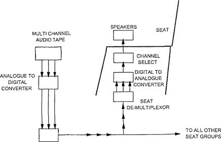
To get the sound to the seats the analogue sound from the video tape is put through an analogue to digital converter and then through a multiplexer to be sent to the individual seat electronic units (fitted under each seat). After demultiplexing and conversion back to analogue in the SEB, the signal is sent to speakers in the seat arm-rest or to a head-phone connection in the arm rest (for speakers in the head phones). Also multiplexed into the system, usually, are sound channels from a multi-channel tape reproducer (figures 4 & 5).
analogue vision
 Fig. 5 SIMPLIFIED MULTIPLEXED SYSTEM
|
Digital System - Real Time
This may use a single projector (three gun primary colour projector) to put the image onto a single screen for each cabin, or TV monitors, or flat screen displays. The sound is transmitted to the seats in a similar way to that described above.
On some aircraft each seat is fitted with a flat screen. This is housed within the seat arm rest or in the back of the seat in front. The channel and volume control selectors are housed within the seat arm or on an attached PCU.
As many as 15 vision channels are provided by a video reproducing unit. These are multiplexed and sent down a common line that runs within the seat tracks fore and aft. The channels are de-multiplexed by the seat electronics unit, and one channel (as selected on the seat PCU) is shown on the flat screen.
The flat screen is very directional and must be viewed in front of the screen to see the picture - which is in colour and of reasonable quality.
The sound signal is multiplexed in a similar way. All sound and vision is in real time, ie, it cannot be played back or put on hold.
Digital Systems - On Demand
A more expensive system but well liked by passengers.
The vision and sound channels are sent to the seat as digital signals from a bank of cd players. There is a cd player for each film channel and for each sound channel. Each cd player has a number of laser beams for signal pick-off - one beam for each seat.
This means that the passenger can select any of the channels (any one of the cd players) and have control of his/her own laser beam. This means that any film can be viewed at anytime. The film can be stopped at any time (for lunch for example) and restarted at the same place later. During this process the particular cd continues to play, it is just the laser beam for that one seat that is controlled.
The system will also have games available from a computer.
A Simple Multiplexed System (Figure 5)
Remember, the whole idea of multiplexing is to send many signals down one transmission line with a consequential weight saving on a multi-line system.
The inputs - example 4 audio signals and 1 vision signal.
The audio tape deck produces four separate entertainment channels. These four signals are converted from their present analogue form to a digital form by an A/D converter - not needed if the original signal is digital.
These four signals now take turns to be transmitted down the one line and this process is carried out by a multiplexor. Each signal will wait its turn to be transmitted and once sent to the seat unit will be de-multiplexed and then wait its turn to be converted back to an analogue signal.
This process of multiplexing/de-multiplexing is carried out at veiy high speed using electronic devices with no moving parts (the drawings show multiplexers /de-multiplexers as switches with pointers - it makes the drawing clearer).
With reference to figure 5 the video for the film produces two analogue signals - one vision and one sound. The vision signal is sent direct to the television set or the three gun colour projector or flat screen displays (fitted in the cabin ceiling panels). The sound signal is put through an A/D converter and then a sub- multiplexor to wait its turn for transmission (a nanosecond or two).
These sound signals are sent to all seats (normally from front to rear) to the seat electronics unit housed under each seat.
Within the seat unit the signal is first de-multiplexed. This is the reverse of multiplexing and puts each separate signal into its own separate store. The signal is then converted to an analogue signal by a D/A converter ready to be understood by the human ear.
Which signal is actually processed depends on the selection, by the passenger, of the seat selector unit.
Once the signal is processed it is sent to a speaker either in the arm rest where air phones channel the noise to the ears or to speakers in a head set connected to the system via a jack in the arm rest.

Date: 2015-12-17; view: 1442
| <== previous page | | | next page ==> |
| Microphone Selector Switches | | | Video Tape Reproducer |