CATEGORIES:
BiologyChemistryConstructionCultureEcologyEconomyElectronicsFinanceGeographyHistoryInformaticsLawMathematicsMechanicsMedicineOtherPedagogyPhilosophyPhysicsPolicyPsychologySociologySportTourism
MEMS Accelerometer
MEMS inertial systems such as accelerometers and gyroscopes can probably be considered the MEMS devices with the largest commercial impact. Driven by the air bag technology, Analog Devices introduced the ADXL50 as the world's first integrated MEMS accelerometer [46, 47]. While the accelerometer is a moving device, the packaging requirements were relatively standard with respect to electronics packaging, e.g. providing electronic interconnects, mechanical and environmental protection, and heat dissipation. A TO5 metal can package, which had demonstrated good reliability in the semiconductor industry, was chosen for the ADXL50.
One of the challenges for the accelerometer industry was the integration of electronics. Two fundamental approaches were followed: integrated single chip solutions using, for example, Analog Device's MEMS® process, and two chip processes, with separate MEMS and electronics die. Motorola has taken the second approach, packaging a capped surface micromachined MEMS structure and an integrated circuit chip in the same plastic package. This is essential since processing the MEMS is not compatible with the processing of the microprocessor control unit. The requirements for the MEMS package are hermetic wafer-level packaging to provide damping control and to protect the MEMS devices from the subsequent dicing and testing; to provide mechanical support; and to isolate stress. In particular, stresses induced by thermal loading due to thermal expansion coefficient mismatches between different packaging materials must be kept at a minimum.
Before the accelerometer can be packaged in a conventional leadframe-and-mold assembly, it must be sealed at the wafer level to be protected. Motorola's wafer-level packaging uses frit-glass bonding [48, 49]. A glass frit/epoxy paste is applied via a screen process, dried and sintered. The cap and the MEMS die are then aligned, pressed together and simultaneously heated above the softening point of the glass. This thermo-compression creates a hermetic seal.
After capping the MEMS die, the accelerometer die and the control signal circuit are mounted to a leadframe flag by standard die bonding techniques and connected via standard wire bonding. The transducer die is passivated with a thin layer of sili-cone gel die coat. In a final step, the two chips are encapsulated in a standard epoxy mold compound. During cooling, the die coat shrinks faster than the mold, and a 25 ( m air gap is created which isolates the transducer die from the surrounding stress.
With the increased use of accelerometers and gyroscopes in the automotive and consumer electronics industry, there was a drive to make smaller devices at a lower cost. Analog Devices developed a wafer-level capping process for their MEMS accelerometers which allows packaging of the device in a very small and thin standard IC package [50,51]. Matched with the MEMS wafer, sensor and die cut cavities are etched into the bottom of the cap wafer. Then, a seal glass is screen-printed onto the cap wafer, and the cap wafer is aligned and bonded to the sensor wafer. At that point, the wafer can be diced and the devices are ready for standard assembly in a wide variety of packages, such as the small footprint LFCSP. Using back-grinding of the MEMS wafer, the device can even be packaged in very thin packages [52]. Figure 12.4 shows three methods for packaging an accelerometer.
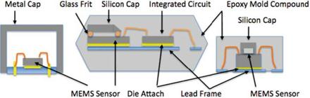
Fig. 12.4 Schematic for an accelerometer packaged in (from left): a TO5 metal can, as capped two-chip package, and after wafer-level capping
12.11.2 Micro-mirror Array
One of the biggest success stories in Micro-Opto-Electro-Mechanical Systems or MOEMS is the Texas Instruments Digital Mirror Display (DMD). First invented in 1987 and introduced in 2000, the technology now powers more than 1,500,000 projectors [53, 54]. DMD is an array of mirror-switches, each 16 ( m squared, which reflect light in and out of the optical path. Major challenges for this system to be overcome are reliability related, hinge fatigue and memory, stiction, and environmental robustness. The package and its optical window in part provide the environmental robustness. The packages for the TI DMD are metal packages with a lid with a high quality optical window seam-welded hermetically to the package. The package itself contains a getter to absorb residual moisture.
For other applications such as optical routers, several ceramic packages such as high-temperature co-fired ceramic (HTCC) as well as low-temperature co-fired ceramic (LTCC) are being used. Advantages of the LTCC are the lower ceramic processing temperatures (850-1000°C), which allows the use of high conductivity metals instead of refractory metals, as well as the good match of the thermal expansion coefficient with silicon [55].
When greater hermeticity is required, especially in cases where the MEMS devices require vacuum seals and high quality windows, some other packages have been designed attaching windows with a gold/titanium/platinum seal ring on a lead-less ceramic chip carrier [56]. The glass window thickness is determined by the package size as well as by the allowable diffusion of hydrogen and helium into the package. Compared to commercial metal-glass covers, these approaches offer better and undistorted optical transmission and the strains and stresses in the transmission windows of such packages have been modeled and measured.
For wafer-level packaging, a similar approach can be taken for packaged accelerometers, using glass frits to bond a cap on the die. For optical transparency, one proposed approach is to anodic bond a silicon frame onto the cover glass, which then is used as the cap over the MEMS die. An hermetic package using this approach has been reported [57].
Date: 2015-02-28; view: 3931
| <== previous page | | | next page ==> |
| Humidity | | | MEMS Microphone |