CATEGORIES:
BiologyChemistryConstructionCultureEcologyEconomyElectronicsFinanceGeographyHistoryInformaticsLawMathematicsMechanicsMedicineOtherPedagogyPhilosophyPhysicsPolicyPsychologySociologySportTourism
Statik registers
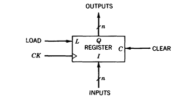
A register is a collection of binary cells used to store a bit-vector. An n-bit register is shown in Figure 2.28. The data input and output are the n-bit vectors I and Q, respectively. The output of the register corresponds to its state. CK is the synchronizing clock. The control inputs are LOAD and CLEAR. If LOAD=1, the next state of the register is defined by the inputs present during the clock pulse; if LOAD=0 the state remains unchanged. That is,

The CLEAR input is asynchronous and serves to load a special state (0, 0 , . . . , 0) into the register. It is commonly used at the beginning of the system operation for initialization purposes. As discussed in Appendix C, the asynchronous inputs should not be used during the synchronous operation.
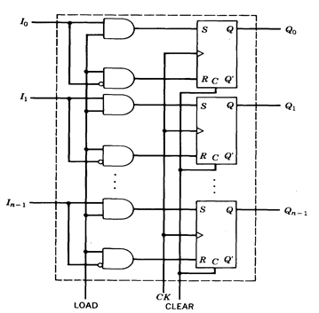
An implementation of a register using SR flip-flops is given in Figure 2.29. Three-state outputs may be provided in order to simplify the use of registers in larger networks. An additional control input, ENABLE, determines whether the register outputs correspond to the state of the cells or have third-state value (TS). A block diagram of a register with three-state outputs is shown in Figure 2.30.

Fig. 2.28 - Block representation of an n-bit register.

Fig. 2.29 - Implementation of an n-bit register.

Fig. 2.30 - n-bit register with three-state outputs.
Date: 2015-01-12; view: 1252
| <== previous page | | | next page ==> |
| Flips types | | | Shift register |