CATEGORIES:
BiologyChemistryConstructionCultureEcologyEconomyElectronicsFinanceGeographyHistoryInformaticsLawMathematicsMechanicsMedicineOtherPedagogyPhilosophyPhysicsPolicyPsychologySociologySportTourism
Hold the clevis and slacken the locknut
Remove the dust boot from the pushrod
Depress the pushrod and remove the circlip
Brakes, wheels and tyres 7»13
|
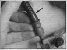
10.2 Flex the brake hoses and check for cracks,bulges and leaks

Inspect the banjo fittings (arrowed)

Renew washers (arrowed) on leaking banjo unions
Make sure the lips on the cup do not turn inside out when they are slipped into the bore.
21 Install and depress the pushrod, then fit the new circlip. making sure it is properly seated in the groove (see illustration 9.15).
22 Install the new dust boot, making sure the lip is seated properly in the groove (see illustration 9.14).
23Fit a new O-ring to the master cylinder hose union, then install the union and secure it with its screw.
Installation
24 Thread the clevis locknut and the clevis onto the master cylinder pushrod, position the clevis as noted on removal and tighten the nut securely (see illustration 9.11).Note that changing the position of the clevis on the pushrod will alter the brake pedal height in relation to the footrest.
25 Install the master cylinder and rear brake light switch onto the footrest bracket, ensuring the clevis aligns with the brake pedal, and tighten the mounting bolts to the torque setting specified at the beginning of this Chapter, Connect the brake light switch spring to the lug on the brake pedal.
26 Install the clevis pin and secure it using a new split pin (see illustration 9.9).Bend the split pin ends securely.
27 Connect the fluid reservoir hose to the master cylinder union and secure it with the clip. Cover the open end of the hose to prevent dirt entering the system.
28 Position the footrest bracket on the frame, install the mounting bolts and tighten the bolts to the specified torque setting.
29 Connect the fluid reservoir to the fluid reservoir hose, align the reservoir with the bracket on the frame and secure the hose with the clip. Temporarily secure the fluid reservoir to the frame with its retaining bolt.
30 Connect the brake hose to the master cylinder, using a new sealing washer on each side of the banjo union. Ensure that the hose is positioned so that it butts against the lug and tighten the banjo bolt to the specified torque setting.
31 Unscrew the fluid reservoir mounting bolt and pull the reservoir clear of the seat cowling to gain access to the tiller cover. Remove the cover, diaphragm plate and diaphragm. Fill
the fluid reservoir with new DOT 4 brake fluid, then fill and bleed the system (see Section 11).
32 Fit the diaphragm, making sure it is correctly seated, the diaphragm plate and the cover onto the reservoir and tighten the cover securely. Fix the reservoir to the frame and install the side panel.
33 Check the operation of the brake before riding the motorcycle.
10 Brake hoses and unions-
inspection and renewal §§
Inspection
1 Brake hose and pipe condition should be checked regularly and the hose(s) renewed at the specified interval (see Chapter 1),
2 Twist and flex the hose(s) while looking for cracks, bulges and seeping fluid. Check extra carefully around the areas where the hose(s) connect to the banjo fittings, as these are common areas for hose failure (see illustration).
3Inspect the banjo fittings; if they are rusted, cracked or damaged, renew them (see illustration).
4 Inspect the banjo union connections for leaking fluid. If they leak when tightened to the specified torque setting, unscrew the banjo bolt and fit new washers (see illustration).
Renewal
5 The brake hose(s) have banjo union fittings on each end. Cover the surrounding area with plenty of clean rag and unscrew the banjo bolt, noting its alignment. Free the hose from any clamps or guides and remove it. Discard the sealing washers on the hose banjo unions. Note:Do not operate the brake lever or pedal while a brake hose is disconnected.
6Position the new hose, making sure it isn't twisted or otherwise strained, and either abut the hose union against the lug on the component casting, or fit it into the slot between two lugs, where present. Otherwise align the hose or pipe as noted on removal. Install the hose banjo bolts using new sealing washers on both sides of the unions.
7Tighten the banjo bolts to the torque settings specified at the beginning of this Chapter. Make sure the hoses are correctly aligned and routed clear of all moving components and reinstall the clamps. On models with a rear disc brake, ensure the rear brake hose is correctly routed through the guide on the caliper bracket.
8 Drain the old brake fluid from the hydraulic system and refill with new DOT 4 brake fluid (see Section 11). Check the operation of the brakes before riding the motorcycle.
11 Brake system- fj$a
bleeding and fluid change
Air bleeding
1 Bleeding the brakes is simply the process of removing air from the brake fluid reservoir, the hose and the brake caliper. Bleeding is necessary whenever a brake system hydraulic connection is loosened, or after a component or hose is renewed, or after the master cylinder or caliper is overhauled. Leaks in the system may also allow air to enter, but leaking brake fluid will reveal their presence and warn you of the need for repair.
2 To bleed the brakes, you will need some new DOT 4 brake fluid, a length of clear vinyl or plastic hose that fits tightly over the caliper bleed valve, a small container partially filled with clean brake fluid, some rags and a spanner to fit the brake caliper bleed valve.
3 Cover the fuel tank and other painted components to prevent damage in the event that brake fluid is spilled.
4 If bleeding the rear brake, unscrew the bolt securing the fluid reservoir to the frame to gain access to the reservoir top.
5 Remove the reservoir top, diaphragm plate and diaphragm and slowly pump the brake lever (front brake) or pedal (rear brake) a few times, until no air bubbles can be seen floating up from the holes in the bottom of the reservoir. Doing this bleeds the air from the master cylinder end of the line. Loosely refit the reservoir cover.
Date: 2016-01-14; view: 803
| <== previous page | | | next page ==> |
| Remove split pin (A) and clevis pin (B) | | | Brakes, wheels and tyres |