CATEGORIES:
BiologyChemistryConstructionCultureEcologyEconomyElectronicsFinanceGeographyHistoryInformaticsLawMathematicsMechanicsMedicineOtherPedagogyPhilosophyPhysicsPolicyPsychologySociologySportTourism
The right-hand caged ball bearing is retained by a circlipDrive the caged ball bearing out from the left-hand side Grease both bearings before reassembly 6«16 Frame, suspension and final drive
GOOD POOR CRACKED
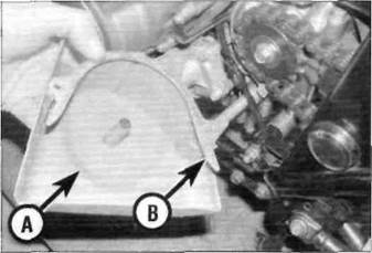
Front sprocket cover (A) and chain guide (B) Check that the ends of the joining link are properly staked
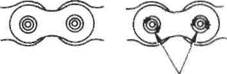
below or by removing the rear wheel and swingarm and detaching it from the front sprocket after the sprocket has been removed from the output shaft. 2 Slacken the drive chain (see Chapter 1). Locate the joining link in a suitable position to work on by rotating the back wheel. 3 Split the chain at the joining link using the chain breaker, carefully following themanufacturer's operating instructions (see also Section 8 in Tools and Workshop Tips in the Reference Section). Remove the chain from the bike, noting its routing around the swingarm. Cleaning 4 Soak the chain in kerosene (paraffin) for Caution: Don't use gasoline (petrol), solvent or other cleaning fluids which might damage its internal sealing properties. Don't use high-pressure water. Remove the chain, wipe it off, then blow dry it with compressed air immediately. The entire process shouldn't take longer than ten minutes - if it does, the O-rings in the chain rollers could be damaged. Installation 5 Unscrew the bolts securing the sprocket cover and remove it and the chain guide (see illustration). 6Install the chain through the chainguard and around the front and rear sprockets, leaving the two ends in a convenient position to work on. 7 Refer to Section 8 in Tools and Workshop Tips in the Reference Section. Install the new joining link from the inside with the four O-rings correctly located between the link plates. Install the new side plate with its identification marks facing out. Measure the amount that the joining link pins project from the side plate and check they are within the measurements specified at the beginning of this Chapter for RK and DID chains. Stake the new link using the drive chain cutting/staking tool, carefully following the instructions of both the chain manufacturer and the tool manufacturer. DO NOT re-use old joining link components. 8 After staking, check the joining link and staking for any signs of cracking (see illustration).If there is any evidence of cracking, the joining link, O-rings and side plate must be renewed. Measure the diameter of the staked ends in two directions and check that they are evenly staked and within the measurements specified at the beginning of this Chapter. 9 Install the front sprocket cover and chain guide, then adjust and lubricate the chain following the procedures described in Chapter 1.
15 Sprockets- check , removal and installation Check
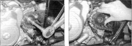
1 Unscrew the bolts securing the front sprocket cover and remove it and the chain guide (see illustration 14.5). 2Check the wear pattern on both sprockets (see Chapter 1, Section 1). If the teeth of either sprocket are worn excessively, renew the chain and both sprockets as a set. Whenever the sprockets are inspected, the drive chain should be inspected also (see Chapter 1). If you are renewing the chain, renew the sprockets as well. 3 Adjust and lubricate the chain following the Front sprocket
4 Unscrew the bolts securing the sprocket cover and remove it and the chain guide (see illustration 14.5). 5Have an assistant apply the rear brake, then unscrew the sprocket bolt and remove the washer (see illustration). 6Slacken the drive chain (see Chapter 1). slide the sprocket and chain off the shaft and slip the sprocket out of the chain. 7 Engage the new sprocket with the chain and slide it on the shaft with its marked side facing outwards (see illustration).Install the sprocket bolt and washer and hand tighten. Adjust the chain tension (see Chapter 1). 8 Have an assistant apply the rear brake, then tighten the sprocket bolt to the torque setting specified at the beginning of this Chapter. 9 Install the front sprocket cover and chain guide, then check and lubricate the chain Frame, suspension and final drive 6*17
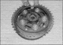
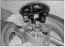
15.11a Pull the sprocket coupling from the hub...
Date: 2016-01-14; view: 517
|
 H30023