CATEGORIES:
BiologyChemistryConstructionCultureEcologyEconomyElectronicsFinanceGeographyHistoryInformaticsLawMathematicsMechanicsMedicineOtherPedagogyPhilosophyPhysicsPolicyPsychologySociologySportTourism
A Radiator upper mounting lug (arrowed)B Rubber shroud locates over radiator brackets (arrowed) Cooling system 3*7
Pump to crankcase bolts (A), pump cover bolts (B), carburettor heater hose Connection (C) and cooling system Drain bolt (0)
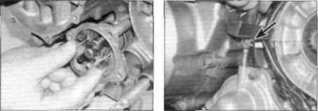
Water pump - check, removal and installation Check 1The water pump is located on the lower left-hand side of the engine (see illustration).Visually check the area around the pump for signs of leakage. 2 To prevent leakage of water from the cooling system to the lubrication system and vice versa, two seals are fitted on the pump shaft. On the underside of the pump body there is also a drainage hole. If either seal fails, this hole should allow the coolant or oil to escape and prevent the oil and coolant mixing. 3 The pump body is only available as a complete assembly. Therefore, if on inspection the drainage hole shows signs of leakage, the pump must be removed and renewed. Checking for freeplay on the pump impeller Removal 4 Drain the cooling system (see Chapter 1). Remove the front sprocket cover to allow easier access to the hoses. Place a suitable container below the water pump to catch any residual oil as the water pump is removed. 5 To remove the pump cover, unscrew the four bolts securing the cover to the pump (the upper and lower bolts also secure the pump to the crankcase), and remove the cover (see illustration 8.1).There is no need to detach the hoses unless you want to. Note the position of each bolt as they are different lengths. Discard the cover O-ring as a new one must be used. 6 Check for freeplay between the pump impeller and the pump body (see illustration).If there is excessive movement the pump must be renewed. Also check for corrosion or a build-up of scale in the pump body and clean or renew the pump as necessary. 7 To remove the pump body, slacken the clamp securing the coolant hose to the pump body and detach the hose. Carefully draw the pump from the crankcase, noting how it fits. Remove the O-ring from the rear of the pump body and discard it as a new one must be used. 8 To remove the whole pump as an assembly, slacken the clamps securing the coolant hoses to the pump cover and body, noting that access to the inner main hose is restricted (detach it from the engine if it proves stubborn). Detach the 8.8a Detach the carburettor heater hose...
8.8b .. ■ and the hoses from the cylinder block (A) and radiator (B) hoses, noting which fits where (see illustrations).Unscrew the two bolts securing the pump assembly to the crankcase (see Step 5) and carefully draw the pump out, noting how it fits. Remove the O-ring from the rear of the pump body and discard it as a new one must be used. Separate the cover from the pump if required and discard the O-ring (see illustration). Installation 9Apply a smear of clean engine oil to the pump body O-ring and install it onto the rear of the pump body, then carefully press the pump body into the crankcase, aligning the slot in the impeller shaft with the oil pump shaft (see illustration).
Date: 2016-01-14; view: 464 |