CATEGORIES:
BiologyChemistryConstructionCultureEcologyEconomyElectronicsFinanceGeographyHistoryInformaticsLawMathematicsMechanicsMedicineOtherPedagogyPhilosophyPhysicsPolicyPsychologySociologySportTourism
And avoid touching the journals on reassemblyB ... and rear tensioner blade falling back into the crankcase during engine reassembly.
28 Transmission shafts and bearings - removal and installation Note:To remove the transmission shafts the engine must be removed from the frame. Removal 1 Remove the engine from the frame (see is in neutral.
2 Unscrew the two bolts securing the input 2*46 Engine, clutch and transmission
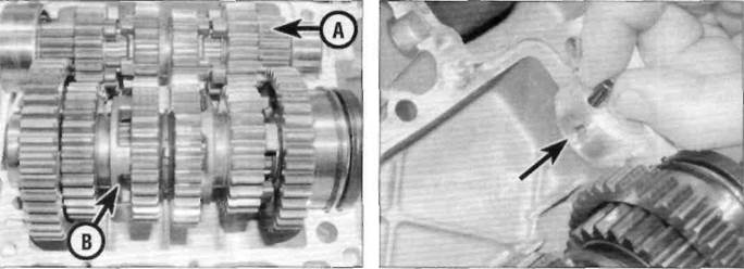
28.3a Input shaft (A) and output shaft (B) B Location of input shaft needle bearing dowel (arrowed)
3Note how the input shaft and the output shaft mesh together (see illustration).Lift the shafts out of the casing. If they are stuck in the casing, use a soft-faced hammer and gently tap on the ends of the shafts to free them. Remove the dowel for the needle bearing on the left-hand end of the input shaft from the crankcase if it is loose, noting how it fits (see illustration).If it is not in its hole in the crankcase, remove it from the bearing on the shaft. 4 Referring to Tools and Workshop Tips (Section 5) in the Reference Section, check
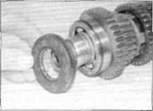
Check the condition of the output shaft oil seal and grease on reassembly the bearings at both ends of the shafts. Renew the bearings if necessary, noting that the bearing on the left-hand end of the output shaft is not available separately and the shaft itself must be renewed. The shafts have to be disassembled for bearing removal and for inspection for wear or damage generally (see Section 29). 5 Remove and check the condition of the Installation 6Clean the bearing seats in both halves of the crankcase with solvent and wipe them dry with a lint-free cloth. Lower the output shaft into the crankcase. Ensure that the bearings locate correctly in their seatings and that the locating ring around the bearing and the lip of the oil seal on the left-hand end of the shaft fit into the slots in the casing (see illustration). 7 Ifremoved, fit the input shaft needle bearing dowel into its hole in the upper crankcase. Lower the input shaft into position, making sure it locates correctly onto the dowel (see illustration). 8Make sure both transmission shafts are correctly seated and their related pinions are correctly engaged. 9 Install the transmission input shaft bearing retainer plate onto the right-hand side of the crankcase. Apply a suitable non-permanent thread-locking compound to the threads of the bolts and tighten them securely (see illustration). Caution: If the transmission shaft bearings are not correctly seated the crankcase halves will not join correctly. 10Lubricate the selector fork grooves with a 50/50 mixture of molybdenum disulphide grease and clean engine oil. Lubricate the gears, shafts and bushings with clean engine oil. 11 Ensure the gears are in the neutral position and check the shafts are free to rotate easily and independently (ie the input shaft can turn whilst the output shaft Is held stationary) before proceeding further. 12 Reassemble the crankcase halves (see Section 20).
Date: 2016-01-14; view: 561
|