CATEGORIES:
BiologyChemistryConstructionCultureEcologyEconomyElectronicsFinanceGeographyHistoryInformaticsLawMathematicsMechanicsMedicineOtherPedagogyPhilosophyPhysicsPolicyPsychologySociologySportTourism
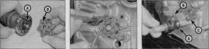
A Ends of the stopper arm return spring (A) and neutral detent on cam (B)19.5b Remove the gearchange stopper 19.5c ... and inspect the return spring (A), Engine, clutch and transmission 2»33 Gearchange shaft circlip (A), circlip groove (B) and pawl mechanism (C) A Prise the old oil seal out with a flat-bladed screwdriver... B .. . press the new seal in with a suitably sized socket
by a circlip. To remove the circlip, slide it down the length of the shaft, do not stretch it over the shaft (see illustration). 7Also check that the shaft return spring locating pin in the casing is securely tightened. If it is loose, remove it and apply a suitable non-permanent thread-locking compound, then tighten it to the torque specified at the beginning of this Chapter. 8 Check the gearchange shaft for straightness and damage to the splines. If the shaft is bent you can attempt to straighten it, but if the splines are damaged the shaft must be renewed. Also check the condition of the shaft oil seal in the casing and renew it if damaged or deteriorated. Lever the old seal out using a flat-bladed screwdriver and press the new seal in squarely with a suitably sized socket (see illustrations). 9Inspect the gearchange shaft selector arm for wear where it bears on the return spring. Also inspect the selector arm pawl mechanism and spring for wear or damage (see illustration 19.6).The gearchange shaft and selector arm mechanism must be renewed as one assembly.
10 Check for wear on the selector cam pins and cam lobes, and the stopper arm and the stopper arm roller. If they are worn or damaged they must be renewed. 11Remove the gearchange cam by unscrewing the bolt in its centre. A recess in the back of the cam locates on apin in the end of the selector drum. Remove the pin for safekeeping (see illustration). Installation 12If removed, install the pin in the end of the selector drum. Install the selector cam, locating the pin in the recess in the back of the cam (see illustration 19.11).Clean the threads of the centre bolt, then apply a suitable non-permanent thread-locking compound. Install the bolt and tighten it to the specified torque setting. 13Fit the stopper arm assembly onto the shoulder on the fixing bolt and screw the bolt into the casing, making sure the ends of the return spring are located correctly over the stopper arm and against the casing (see illustration 19.5a).Position the stopper arm roller in the neutral detent on the selector cam and ensure that the stopper arm is free to move and is returned by the pressure of the spring (see illustration). 14Check that the gearchange shaft return spring is properly positioned and that the circlip is in its groove. Slide the washer onto the shaft. Lightly grease the inside of the gearchange shaft oil seal in the left-hand side of the engine and slide the shaft into place from the right-hand side (see illustration). 15Locate the selector arm pawls onto the pins on the selector cam and the ends of the return spring onto each side of the locating pin (see illustration 19.4a). 16Align the gearchange lever with the punchmark on the gearchange shaft and refit the lever. Tighten the lever pinch bolt to the torque setting specified at the beginning of this Chapter. 17 Install the clutch (see Section 15).
20 Crankcase halves- separation and reassembly Note 1: To separate the crankcase halves, the engine must be removed from the frame. Note 2:If the crankcases are being separated to inspect the crankshaft without removing it, or to inspect or remove the transmission shafts, the cylinder head can remain in place. However, if removal of the crankshaft or pistons and connecting rods is intended, full disassembly of the top-end is necessary. The gearchange mechanism external components can remain in place unless the selector drum and forks are being removed. Separation 1 To access the pistons, connecting rods, camchain and guides, crankshaft, balancer shaft, bearings, transmission shafts and the selector drum and forks, the crankcase must be split into two parts. 2 Remove the engine from the frame (see Section 5). Before the crankcase can be split the following components must be removed:
a) Valve cover (Section 7) (see Note 2). b) Camshafts (Section 9) (see Note 2). c) Cylinder head (Section 10) (see Note 2). d) Starter motor (Chapter 9).
Date: 2016-01-14; view: 471
|