CATEGORIES:
BiologyChemistryConstructionCultureEcologyEconomyElectronicsFinanceGeographyHistoryInformaticsLawMathematicsMechanicsMedicineOtherPedagogyPhilosophyPhysicsPolicyPsychologySociologySportTourism
Microscopic description
Defect studies (in the laboratory) are performed by the way of Transmission Electrom microscope (TEM) equipments, since defects are at the scale of the atomic distances. Their understanding is important because they at the base of material behaviours. There are 3 kinds of defects in crystals : point defects (dimention 0) , linear (dimention 1) and bidimentional (dimention 2).
ü Point defects can be of 3 kinds : - vacant atomic sites ; - intersticial atomic sites (usually a small atom occupying an «empty » space of the lattice), and - substitution sites (usually an exotic atom replacing a « normal» atom of the structure). Among these point defects, the most important one (under the point of view of plastic deformation) is the vacant site … since the displacement of a vacant site represents the opposite displacement of an atom (of the structure) : this is at the base of atomic diffusion in minerals.
ü Bidimentional defects are usually represented by stacking faults. The easiest representation of a stacking fault is the stacking of 2D-hexagonal arrays of atoms that make either the AB/AB/AB atomic successions (cubic arrangement), or the ABC/ABC/ABC … successions (hexagonal arrangement). Any rupture among these successions of atomic planes corresponds to a stacking fault. For example : ABC/ABC/AB/AB/ABC/ABC.
Excercice : Examine the case of the stacking of oranges in front of a shop.
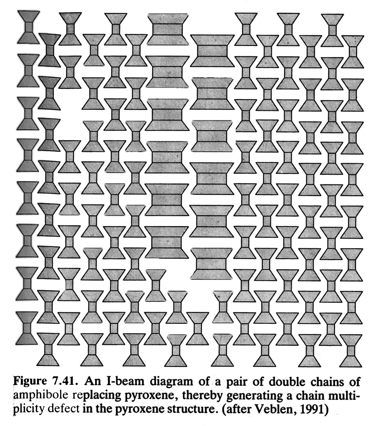
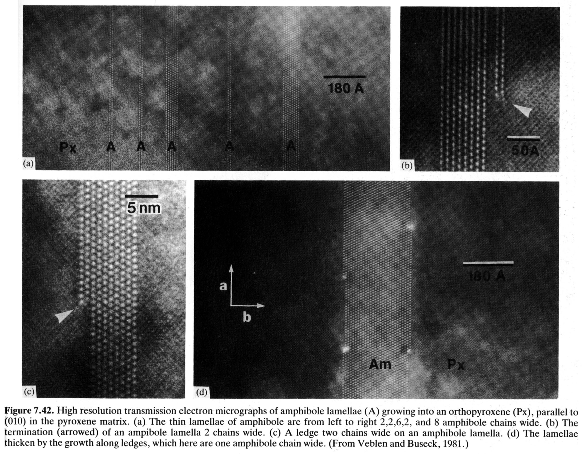
Stacking faults often take place when phase transformations appear, for example for the transformation of pyroxene into amphibole (by the so-called retromorphic metamorphism from granulite facies to amphibolite facies : Figure and TEM image).
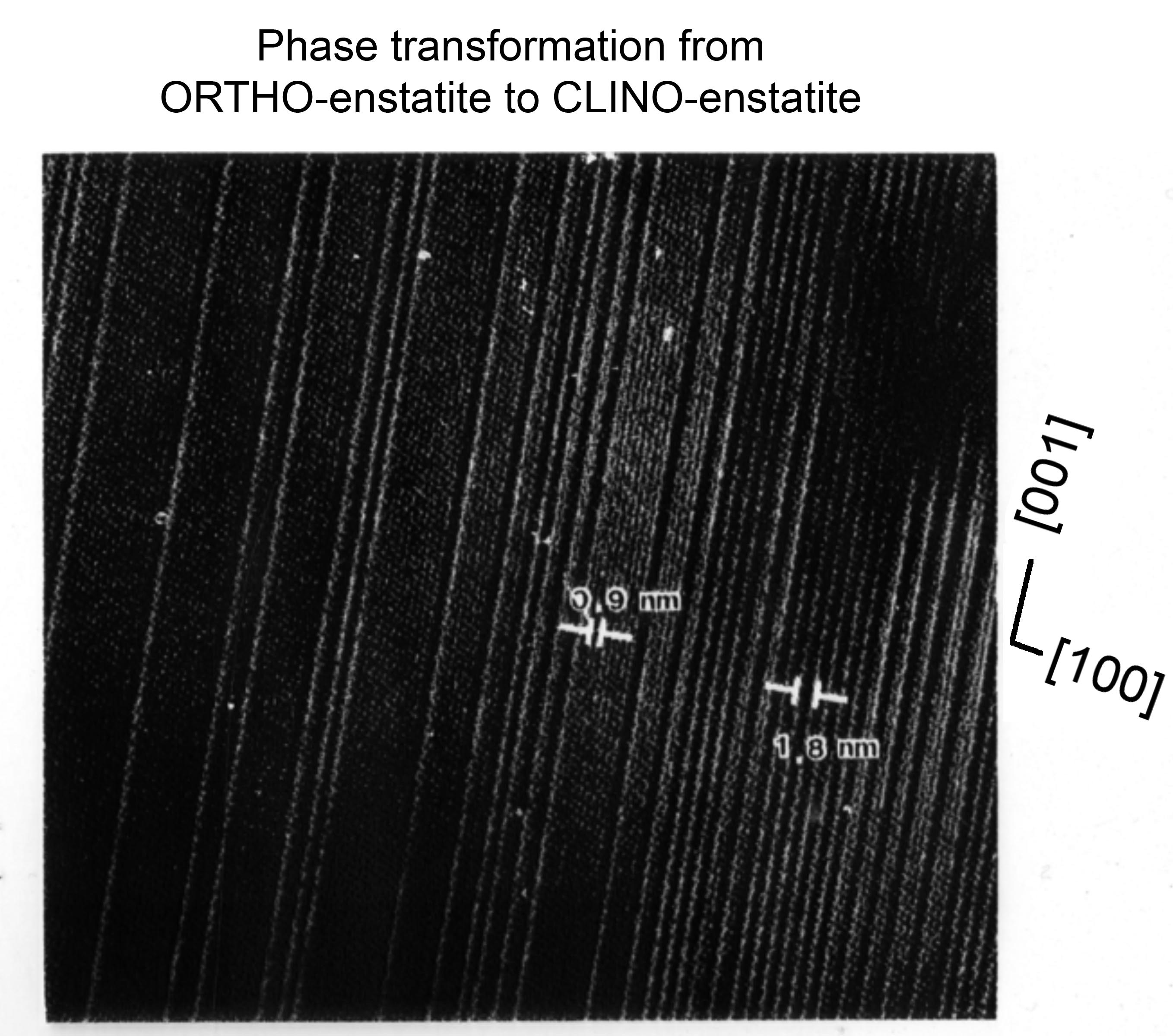
The transition from ortho-enstatite (orthorhobic pyroxene, atomic spacing 9.1A) into clino-enstatite (atomic spacing 18.2A) gives another example of stacking fault due to shearing parallel to (100) (Figure).
ü Linear defects, or dislocations
The intracrystalline deformation of minerals (the usual mode of deformation at moderate to high-T) is due to the displacement of the linear defects contained in them.
Basically a dislocation, a one dimentional defect (a line of atoms), is the edge of an atomic plane. There are two kinds of dislocations : edge dislocations and screw dislocations.
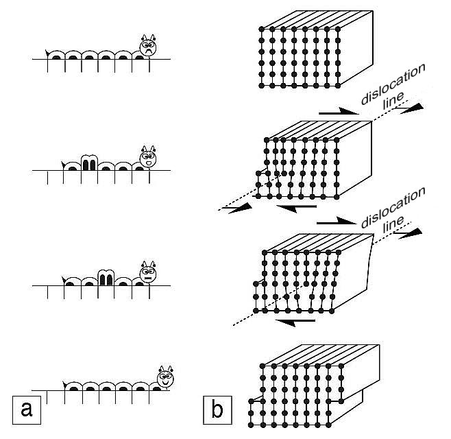
v Edge dislocations
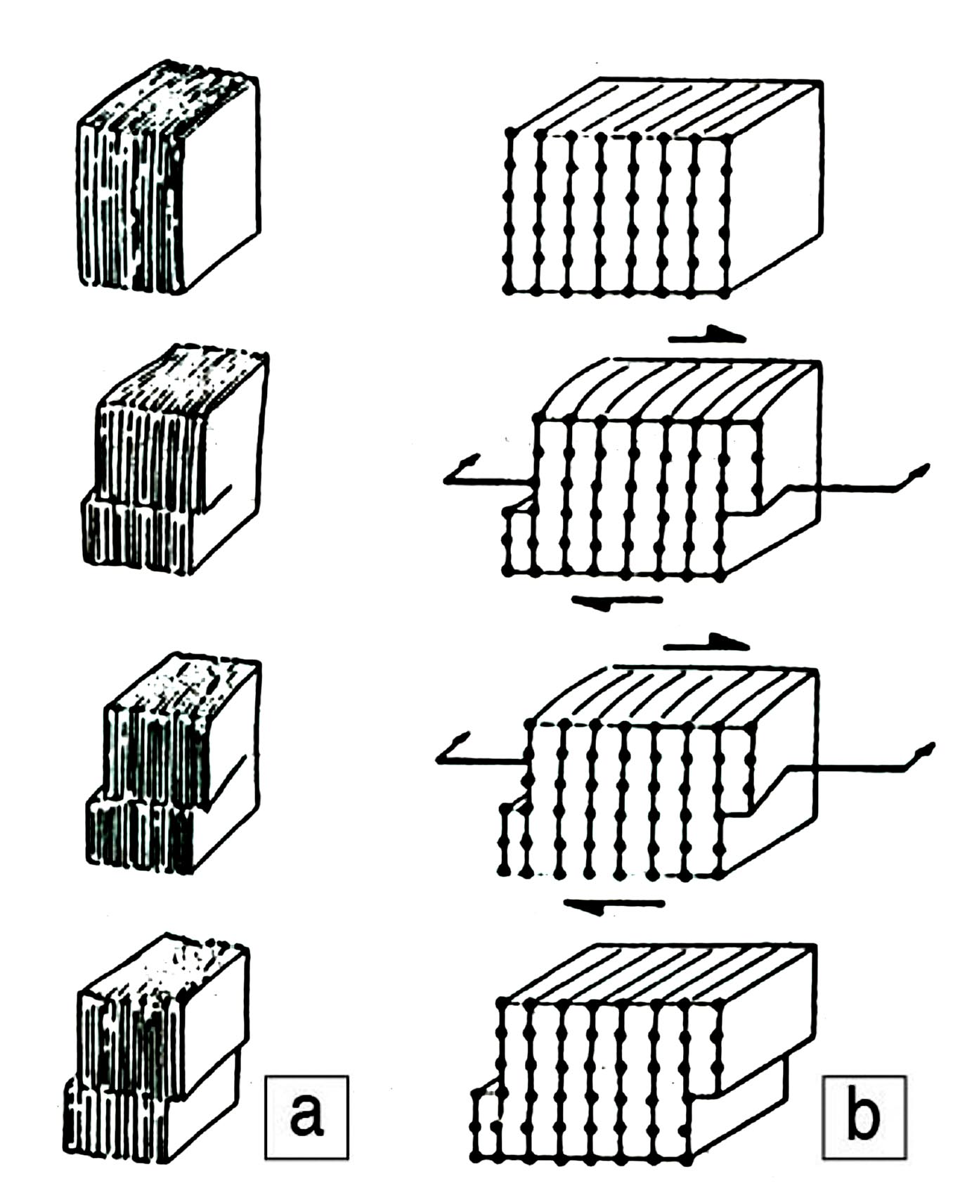
Figure. Edge dislocation. Progession of a caterpillar (a) mimicts the propagation of an edge dislocation (b). At the end of the progession, the upper-half crystal is displaced (to the right or left pending on the dislocation sign) by one inter-atomic distance with respect to the lower-half of the crystal.
v Screw dislocations
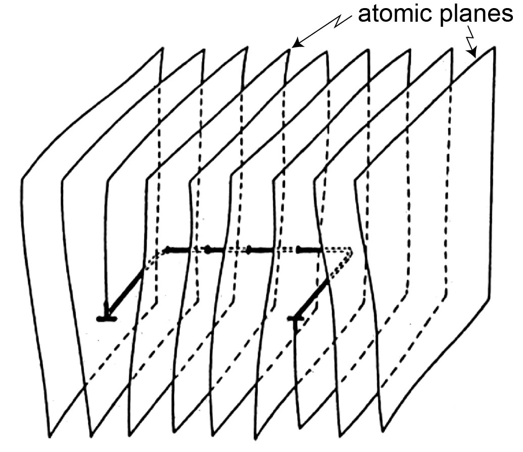
Figure. Screw dislocation. Tearing of a package of paper from the front-side to the back-side (a) mimicts the propagation of a screw dislocation. When the screw diloscation leaves the crystal, the upper-half of the crystal is displaced by one inter-atomic distance with respect to the lower-half crystal.
This unit displacement in a crystal (one inter-atomic distance) is called the Burgers’ vector (Figure). An edge dislocation is perpendicular to the Burgers’ vector, while a screw dislocation is parallel to it. The displacement of a dislocation is always perpendicular to the dislocation.
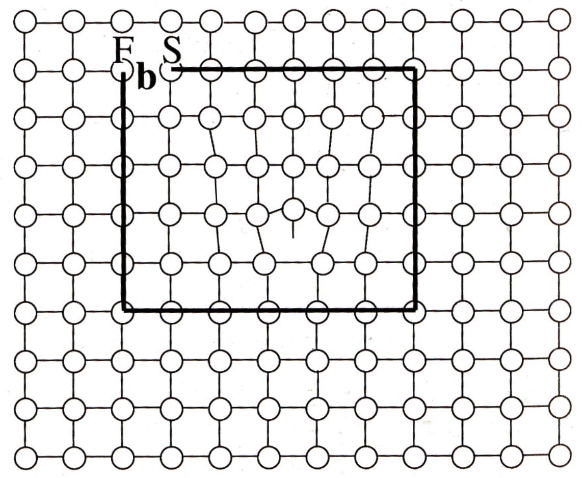
Figure. Determination of the Burgers vector b of a dislocation by carrying out a Burgers circuit. Starting from a point S a circuit with equal atomic steps in opposite directions (in this case 6 x 5 atomic steps) around the dislocation core, terminates at point F. The failure to close the circuit indicates the presence of a dislocation, and the Burgers vector is defined as the vector FS.
v Loops
In fact, dislocations form dislocation loops, combines edge and screw dislocations, hence have edge components, screw components and mixed components. Loops grow perpendicularly to itself (Figure).
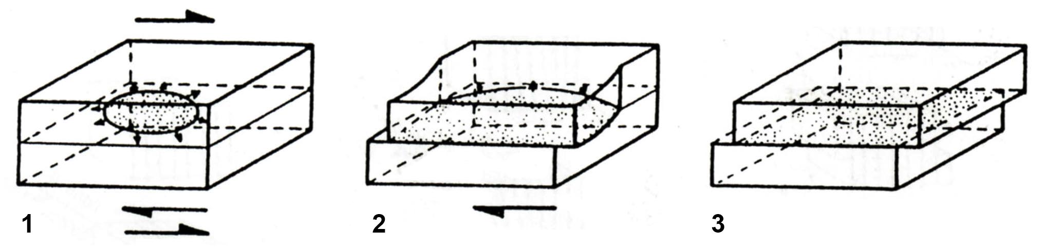
Figure. Dislocation loop, made of edge, screw and mixed segments, expanding in its plane, triggered by a shear stress. When the loop leaves the crystal, the upper-half of the crystal is displaced by one inter-atomic distance with respect to the lower-half crystal.
v Edge-screw relationships (loop)
Figure. Half dislocation loop. From a positive edge (left) to a negative edge (rifgt) relayed by a screw.
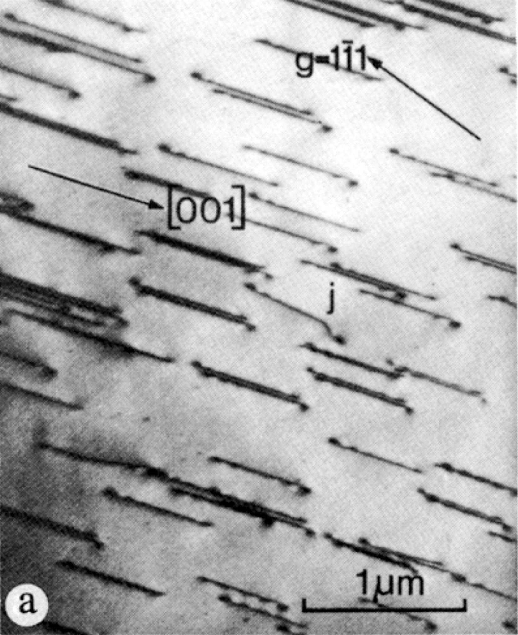
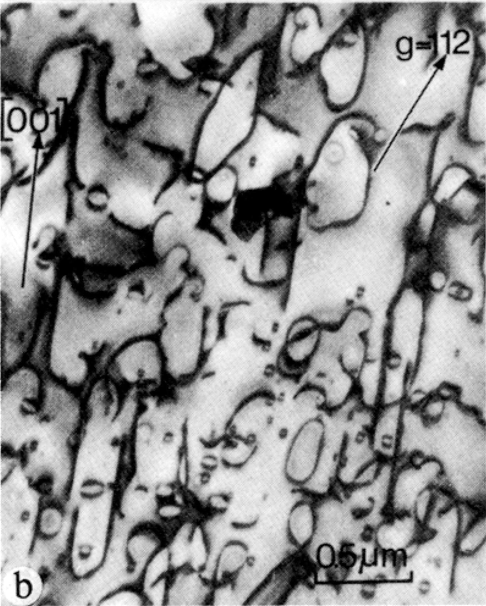
v TEM images of dislocations
Figure. Dislocations in olivine. Left : straight crew dislocation (deformation at 600°C). Right : dislocaton loops (deformation at 1000°C). From Phakey et al. (1972).
Date: 2015-01-29; view: 4274
|