CATEGORIES:
BiologyChemistryConstructionCultureEcologyEconomyElectronicsFinanceGeographyHistoryInformaticsLawMathematicsMechanicsMedicineOtherPedagogyPhilosophyPhysicsPolicyPsychologySociologySportTourism
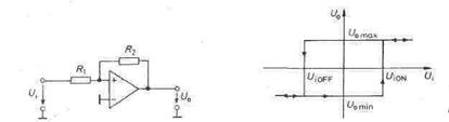
Non-inverting Schmitt triggerThe input signal for the Schmitt trigger in Fig. 2.70 can also be applied to the low end of the feedback voltage divider when at the same time the input is grounded. The new configuration is the non-inverting Schmitt trigger in Fig. 2.73.
If a large positive input voltage Ui is applied, U0 = U0max . When reducing Ui , Ua does not change until VP crosses zero. This is the case f the input Fig. 2.73 - Non-inverting Schmitt. Fig. 2.74.- Transfer characteristic. Switch-on level: Switch-off level: Hysteresis:
voltage
The output voltage jumps to Uomin as soon as Ui reaches or fails below this value. The transition is initiated by Ui but is then determined only by the positive feedback via R2. The new state is stable until Ui returns to the level
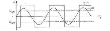
Figure 2.75 depicts the time function of the output voltage for a sinusoidal input. Since, at the instant of transition, VP = 0, the formulae for the trigger level have the same form as those for the inverting amplifier.
Fig. 2.75 - Voltage waveshapes of the non-inverting Schmitt trigger.
Date: 2015-01-12; view: 863
|