CATEGORIES:
BiologyChemistryConstructionCultureEcologyEconomyElectronicsFinanceGeographyHistoryInformaticsLawMathematicsMechanicsMedicineOtherPedagogyPhilosophyPhysicsPolicyPsychologySociologySportTourism
Window comparator
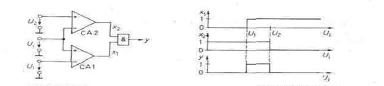
A window comparator can determine whether or not the value of the input voltage lies between two reference voltage levels. Figure 1.66.shows that two comparators are used to decide whether the input voltage is above a lower and below an upper reference voltage. When this condition arises, both comparator amplifiers produce Boolean "one", the and gate providing the defined logic evaluation. The characteristics in Fig. 1.67 illustrate the operation.
Fig, 1.66 - Window comparator. Fig. 1.67 - Variables as a function of the. input voltage y = 1 for U1 <Ui<U2
Digital comparators
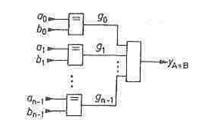
Comparators check two numbers, A and B, against one another, the relations of interest being A = B, A > B and A < B. We shall first consider comparators which determine whether two binary numbers are equal (identity comparators). The criterion for this is that all corresponding bits of the two numbers are identical. The comparator will produce at its output a logic 1 if the numbers are equal, otherwise a logic 0. In the simplest case, the two numbers consist of only one bit each; to compare them, the equiv operation (exclusive-nor gate) may be used. Two AT-bit numbers are compared bit by bit using an equiv circuit for each binary digit and the outputs are combined by an and gate, as shown in Fig. 1.68. Fig. 1.68 - Identity comparator for two N-bit numbers.
IC-types: 2x8 inputs: SN74LS688 (TTL) from Texas-Instr. 2x9 inputs: Am29809 (TTL) from AMD. 2 x 10 inputs: SN74LS460 from MMI.
Comparators have a wider range of application if, in addition to indicating equality, they can also determine which of two numbers is the larger. Such circuits are known as magnitude comparators. To enable a comparison of the magnitude of two numbers, their code must be known, and for the following, we assume that both numbers are straight binary coded, i.e. that
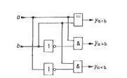
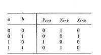
The simplest case is again that of comparing two single-bit numbers. The formulation of the logic functions is based on the truth table of Fig. 1.69. From these, we can directly obtain the circuit in Fig. 1.70. The following algorithm is used for comparing numbers consisting of more than one bit: To begin with, the most significant bit (MSB) of A is compared with the MSB of B. If they are different, these bits are sufficient to determine the result. If they are equal, the next lower significant bit must compared, etc. If the identity variable of digit is denoted by g, as in Fig. 1.68, the magnitude comparison of an W-digit number is given by the general relation
Fig. 1.69 - Truth table of a 1-bit magnitude Fig. 1.70 - 1-bit magnitude comparator. comparator.
1C types: for 5-digit comparison: MC 10166 (ECL) for 8-digit comparison: SN 74 LS682 . . . 689 (TTL).
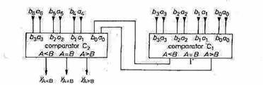
The circuits can be cascaded serially or in parallel, Fig. 1.71 showing the serial method. When the 3 most significant bits are the same, the outputs of comparator C1 determine the result, as they are connected to the LSB inputs of comparator C2 (LSB = least significant bit). When comparing many-bit numbers it is better to employ parallel cascading, as in Fig. 1.72, since the propagation delay time is shorter.
Fig. 1.71 - Serial magnitude comparator.
Fig. 1.72 - Parallel magnitude comparator. Date: 2015-01-12; view: 1203
|
 .
.
 .
.