CATEGORIES:
BiologyChemistryConstructionCultureEcologyEconomyElectronicsFinanceGeographyHistoryInformaticsLawMathematicsMechanicsMedicineOtherPedagogyPhilosophyPhysicsPolicyPsychologySociologySportTourism
Code converters
A simple method of binary-to-BCD conversion consists of having a straight binary counter and a decimal counter operating in parallel. If the two counters are started at zero and then stopped when the binary number to be converted is reached, the corresponding BCD number will be available at the output of the decimal counter. The disadvantage of this method is that up to 2N counting steps have to be executed in order to convert an N-digit binary number. The method described below, on the other hand, requires only N computing steps. For arithmetic operations in BCD code, results may arise containing the decimal "digits" 10dec. to 15dec. Such unintended digits are called pseudo-tetrads (pseudo combinations). To correct for them, they must be reduced by 10dec = 10102 and the next higher tetrad increased by 1. This correction can also be achieved by adding 6 = 01102 to the pseudo-tetrad, as shown by the following example:
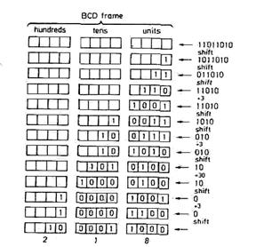
The above example illustrates the rule for converting a 4-bit straight binary number to a BCD number. Numbers up to and including 9 remain unchanged. Numbers over 9 must undergo the pseudo-tetrad correction. Binary numbers of more than 4 bits are treated accordingly: beginning with the most significant bit (MSB), the straight binary number is shifted from right to left into a BCD "frame", as shown in Fig. 1.48. If a 1 crosses the boundary between the units- and the tens-column, an error is incurred. This is because, for the straight binary number, the weighting changes due to the shift from 8 to 16, whereas for the BCD number it changes only from 8 to 10. After such a shift, the BCD number has become too small by 6. To allow for this, a 6 must be added whenever a 1 crosses the boundary. Similarly, a 6 must be added in the tens-column when a 1 is transferred to the hundreds-column. The resulting BCD number then has the correct value but may still contain pseudo-tetrads. To avoid this, any pseudo-tetrads that do occur are immediately corrected after every shift by adding 6 to the decade in question and carrying 1 to the next decade. Both corrections require the same arithmetic operation, that is the addition of 6.
Fig. 1.48. - Straight binary-to-BCD conversion; 218 dec as an example.
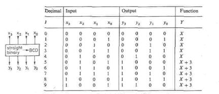
Instead of adding 6 after the shift, one can equally well add 3 beforehand, since it can be ascertained before the shift whether or not a correction will be necessary: if the value of a tetrad is smaller than or equal to 4 = 01002, the subsequent shift will result neither in a I crossing the column boundary nor in a pseudo-tetrad. The tetrad can therefore be shifted to the left unchanged. If the value of the tetrad before the shift is 5, 6 or 7, there again is no boundary crossing, as the most significant bit is zero. However, the pseudo-tetrads ten, twelve, fourteen, or eleven, thirteen, fifteen may arise depending on whether the next bit entering the frame is 0 or 1. In these cases a pseudo-tetrad correction is necessary, i.e. 3 must be added before the shift. If the value of the tetrad before the shift is 8 or 9, the "boundary crossing of the 1 must be corrected, giving the correct tetrads six or seven, or eight or nine, after the shift. Because of the immediate pseudo-tetrad correction, values higher than nine cannot arise. All possibilities are now taken care of, and we obtain the correction table in Fig. 1.49. The conversion of a straight binary to the corresponding BCD number can be implemented by left shifting the straight binary into a shift register divided into 4-bit blocks (decades). A correction circuit is connected to each decade, which alters the contents of the register according to the truth table in Fig. 1.49. before the next shift is carried out. Instead of a solution involving sequential logic circuits, combinatorial logic circuitry can be employed if the shift operation is performed by appropriate wiring. This possibility is shown in Fig. 1.50. Rather than shifting the number from right to left, the BCD frame may be shifted from left to right and each tetrad corrected according to the table in Fig.1.49. In order to be able to hard-wire the frame shift, an individual correction
Fig. 1.49 - Correction system for the straight binary-to-BCD conversion.
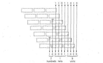
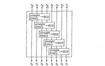
Fig. 1.50 - Straight binary-to-BCD conversion using correction networks. The values shown refer to the example of 218 decnetwork is necessary for each decade and each shifting "step". The total circuit may be simplified by omitting a correction network whenever fewer than 3 bits are applied at the input, as in this case a correction is definitely not required. Figure 1.50 shows the combinatorial logic circuit for the conversion of an 8-bit binary number, where the omitted elements are drawn with dashed lines. The circuit can be extended to deal with larger numbers by expanding its characteristic pattern. The numbers in the diagram apply to the example of Fig. 1.48 and illustrate the conversion procedure. The correction network is available as a manufacturer-programmed, 256-byte ROM (SN 74 S 485). Five networks are combined to form a block, as in Fig. 1.51. As comparison with Fig. 1.50 shows, an 8-digit binary number can be converted using two ICs. A 16-digit binary number requires eight ICs.
Fig. 1.51 - Functional diagram of binary-to-BCD converter SN74S4RS.
Date: 2015-01-12; view: 2340
|