CATEGORIES:
BiologyChemistryConstructionCultureEcologyEconomyElectronicsFinanceGeographyHistoryInformaticsLawMathematicsMechanicsMedicineOtherPedagogyPhilosophyPhysicsPolicyPsychologySociologySportTourism
AntennaThe antenna is a sector type. It covers an angular area at either 90o, 60o, 45oor 30o. Several sector antennas (4, 6, 8 or 12), each with its own RFU, may cover a whole service area (cell). BS Powering The BS is powered by a DC standard source (48V) to the indoor unit. Terminal Station (TS) The following diagramm shows a general view of the Terminal Station.
Figure 7. Terminal Station Overview
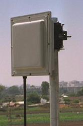
A Terminal Station consists of a single BU (adapted to TS operation) and an integrated RFU and antenna subsystem. Basic Unit (BU) The main building blocks of the BU are: the modem, the telecom interface cards and the IF module. Each BU converts the IF signal to telecom voice/data towards the telecom port, and vice verse. The modem is implemented on the motherboard, which is identical on all BUs. The interface cards and the IF module are implemented on daughterboards, and therefore allow maximum flexibility. Each BU contains up to three interfaces to the telecom switches (ISDN, Frame Relay, etc.). A single coax cable carries IF signal, that connects it to the RFU which is installed at the roof top. RFU The RFU converts IF to RF. The antenna is an integral part of the RFU. The antenna is a directive printed circuit type, that is directed towards the BS location. The TS is powered either by a DC standard source (48V) or an AC source to the indoor unit. The following picture shows a general view of the Terminal Station.RFU
Figure 8. RFU Overview
Date: 2015-01-11; view: 603
|