CATEGORIES:
BiologyChemistryConstructionCultureEcologyEconomyElectronicsFinanceGeographyHistoryInformaticsLawMathematicsMechanicsMedicineOtherPedagogyPhilosophyPhysicsPolicyPsychologySociologySportTourism
Experiment 2. Determination of equivalent resistance of parallel connected resistors
Assemble the circuit shown in fig. 3. 2.
Turn on the modeling process. Using switches the scheme, measure the resistance of a single resistor, then the second and the resistance of parallel connected resistors.
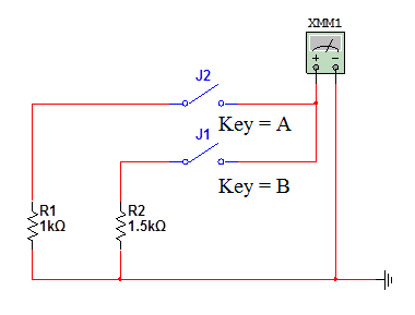
Fig. 3. 2. The scheme to determine the equivalent resistance of two parallel connected resistors
The results of measurements and calculations appears in the table. 3. 2.
Table 3. 2
Results determination of the resistance of resistors
| Rooms closed switches | The measured value resistance | The Calculated value resistances |
| 1,2 |
Compare results of measurements and calculations.
Experiment 3. Determination of the equivalent EMF of two series-connected sources
Follow the connection elements according to the scheme depicted in fig. 3.3.
Switching the sources, measure the equivalent EMF and calculate them.
The results of measurements and calculations appears in the table. 3. 3.
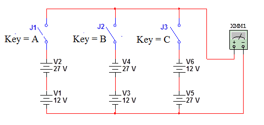
Fig. 3. 3. The scheme to determine the equivalent EMF connected in series signal sources
Table 3. 3
The results of determining the values of the EMF
| Closed numbers switches' | The Measured value of the EMF | The Calculated EMF value |
Compare the results of measurements and calculations.
Experiment 4. Determining the equivalent currents of two parallel-connected sources
Assemble the circuit according to fig. 3. 4.
Turn on the circuit modeling and, alternately closing one of the switches, measure the equivalent currents, and calculate these currents.
The results of measurements and calculations appears in the table 3. 4.
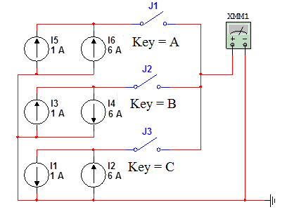
Fig. 3. 4. The scheme for determining equivalent current of two parallel connected sources
Table 3. 4
The results of measurement of currents
| Rooms closed switches | The Measured value of the current | The calculated value of current |
Compare the results of measurements and calculations.
Date: 2018-08-27; view: 28798
| <== previous page | | | next page ==> |
| Experiment 1. Measuring the resistance of resistors | | | Brief theoretical information |