CATEGORIES:
BiologyChemistryConstructionCultureEcologyEconomyElectronicsFinanceGeographyHistoryInformaticsLawMathematicsMechanicsMedicineOtherPedagogyPhilosophyPhysicsPolicyPsychologySociologySportTourism
Angle of SR CornersAs previously mentioned, the SRs are located in the crossover or branches of vessels (mostly thick vessels). Hence, we define the corners of a SR as the points that belong to the boundary of selected SR and have been located in a crossover or a bifurcation. To extract these corner points, we propose an efficient algorithm based on the morphological properties of the SRs that are described in the following, 1) Perform the morphological dilation on 2) Perform 3) Find the nonzero pixels in the image 4-a) Move the extracted candidate points in the outward orientation of selected SR through the skeleton segmented image ( 4-b) Cut the connectivity of selected SR with blood vessel tree by subtracting the dilated image (Fig. (4-b)) from segmented blood vessel image, 4-c) Label the nonzero components of 4-d) Eliminate the candidate corner points which the value of its corresponding moved point is zero in the image of (Fig. (4-i)). By using this strategy, the extracted corner points which happened on thin vessels around the selected SR are removed. 5) Merge the corner points which are close to each other (three pixels). 6) Find the closest point on the boundary to the resulted point and replace it by this point on the boundary. Fig. (4-j) shows the resulted corner point with blue star. 7) Calculate the angle of corner points on the selected SR boundary as in the following. Assume
where To extract other shape features from each SR, we should soften the boundary of selected SR to reduce the effect of noise in the boundary segmentation process. For this purpose, we apply a moving average filter on all pixels of SR’s boundary. Assume that
where
(a) (b) (c)
(d) (e) (f)
(g) (h) (i)
(j) Fig. 4: Extraction of the feature of angle of SR corners. (a) A sample of the selected SR, (b) Dilated version of the selected SR in (a), (c) Subtraction of (a) from (b), (d) Skeleton segmented image of blood vessels, (e) Skeleton of extracted blood vessels around SR, (f) Corner point candidates of SR, (g) Moved candidate corner points for 10 pixels, (h) Removing small components of vessel tree corresponding thin vessels around selected SR, (i) Eliminating candidate corner points on thin vessels and (j) Calculating the angle of corner points of SR as it is described in Eq. (3). Centroid Distance In the shape-based object recognition application, the centroid is defined as the gravity center of the object [34]. This feature is defined based on the distance of boundary points and the centroid
where
where Date: 2016-04-22; view: 681
|
 (binary image of
  SR) using a disk shape structure element (
  ) with the size of 5 pixels as,
  (Fig. (4-b)).
 , where
  (Fig. (4-c)) is a binary image obtained by subtracting
  and
and  (Fig. (4-d)) represents the skeleton of extracted blood vessels. Fig. (4-e) shows the result of this process (
  ).
). , (Fig. (3-b)) as,
  (Fig. (4-g)).
 and remove the small components with area less than 100 pixels. So, smaller components that represent the thin vessels are removed (Fig. (4-h)).
 be a set of the corner points of the selected SR in clockwise direction,
  (
(  ), where
  is the number of extracted corner points. For each corner point,
  , the angle between the left side vector
  and the right side vector
  is then computed as,
 (3)
(3) and
and  are obtained by averaging ten left-handed neighborhood pixels and ten right-handed neighborhood pixels of concerned corner point (
  is gained. Fig. 4 shows the middle results of our algorithm to extract the feature of angle of SR corners.
 ,
,  , denotes the coordinates of boundary pixels of the selected SR as a closed sequence with
  ,
,  , are calculated as follows,
 ,
,  (4)
(4) is the size of filter. Hereinafter, we extract the shape features from the filtered sequence instead of the pixel coordinates.
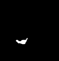


 of the selected SR as,
 (5)
(5) is the coordinate of each boundary pixel and
  ,
,  (6)
(6) represents the total number of points that are belong to the selected SR consisting of the inside and boundary points. Fig. 5 demonstrates the extraction of this feature on a sample of the selected SR.