CATEGORIES:
BiologyChemistryConstructionCultureEcologyEconomyElectronicsFinanceGeographyHistoryInformaticsLawMathematicsMechanicsMedicineOtherPedagogyPhilosophyPhysicsPolicyPsychologySociologySportTourism
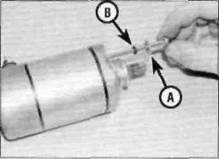
Horn wiring connectors (arrowed)Disconnect the starter motor lead (arrowed) Electrical system 9»17
Starter motor terminal cover Starter motor earth lead (arrowed) Withdraw the starter motor and discard the O-ring (arrowed)
11Connect the negative (-ve) lead last when reconnecting the battery. 28 Starter motor- ||> removal and installation 1§ Removal 1 The starter motor is mounted on the crankcase behind the cylinders. 2 Disconnect the battery negative (-ve) lead (see Section 3). 3 Peel back the rubber terminal cover on the starter motor, then remove the nut securing the starter lead to the motor terminal and detach the lead (see illustration).
Ensure O-ring seats in its groove (arrowed)
4Unscrew the two bolts securing the starter motor to the crankcase, noting the earth lead attached to the rear bolt (see illustration). 5Slide the starter motor out from the crankcase and remove it from the machine (see illustration).Remove the O-ring on the end of the starter motor body and discard it as a new one must be used. Installation
6 Install a new O-ring on the end of the starter motor body and ensure it is seated in its groove (see illustration).Apply a smear of engine oil to the O-ring to aid installation. 7 Manoeuvre the motor into position and slide it into the crankcase. Ensure that the starter motor teeth mesh correctly with those of the starter idle gear. Install the mounting bolts, not forgetting to fit the earth lead with the rear bolt, and tighten them securely (see illustration 28.4). 8Connect the starter lead to the motor terminal and secure it with the nut. Hold the lower nut on the terminal with an open-ended spanner while tightening the top nut (see illustration).Make sure the rubber cover is correctly seated over the terminal. 9 Connect the battery negative (-ve) lead. 29 Starter motor- disassembly, ^ inspection and reassembly ^ Disassembly 1 Remove the starter motor (see Section 28). 2 Note the alignment marks between the main housing and the front and rear covers, or make your own if they aren't clear (see illustration). 3Unscrew the two long bolts, noting how the D-shaped washers locate, and withdraw them from the starter motor (see illustration).Discard their O-rings as new ones must be used. 4 Wrap some insulating tape around the teeth on the end of the starter motor shaft - this will protect the oil seal from damage as the front cover is removed. Remove the front cover from the motor and remove the tabbed thrust washer from inside the front cover (see illustration).
Date: 2016-01-14; view: 598
|