CATEGORIES:
BiologyChemistryConstructionCultureEcologyEconomyElectronicsFinanceGeographyHistoryInformaticsLawMathematicsMechanicsMedicineOtherPedagogyPhilosophyPhysicsPolicyPsychologySociologySportTourism
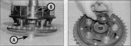
Drive out the spacer with a long socketOn R and T models, remove the brake backplate assembly. 28 Lift the sprocket coupling out of the wheel, noting how it fits, then prise the O-ring out of the groove on the left-hand side of the hub; discard the O-ring as a new one should be fitted. 29Using a flat-bladed screwdriver, lever out the grease seal from the outside of the coupling (see illustration). 30Remove the spacer from the inside of the sprocket coupling bearing, noting how it fits. The spacer could be a tight fit and may have to be driven out using a suitable long socket or piece of tubing (see illustration). 31Support the coupling on blocks of wood and drive the bearing out from the inside using a bearing driver or socket. 32Refer to Steps 6 to 8 above and check the bearing. 33Thoroughly clean the bearing seat then install the bearing into the coupling, with the marked or sealed side facing out. Using the old bearing, a bearing driver or a socket large enough to contact the outer race of the bearing, drive it in until it is completely seated. 34Install the spacer into the inside of the coupling bearing. If the spacer is a tight fit it will be necessary to support the inner race ol the bearing when driving the spacer in (see illustrations). 35Install the grease seal in the outside of the coupling (see Step 10) (see Illustration). 36Check the sprocket coupling/rubber damper (see Chapter 6).
A The spacer fits on the inside of the coupling bearing B Support the inner bearing race with A suitable socket (A) while driving the Spacer in (B) 17.35 Install thegrease seal Brakes, wheels and tyres 7*21
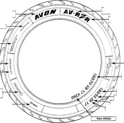
TYRE CONSTRUCTION DETAILS (NOT REQUIRED IN UK) NORTH AMERICAN TYRE IDENTIFICATION NUMBER NORTH AMERICAN DEPARTMENT OF TRANSPORT COMPLIANCE SYMBOL ARROW DENOTING THE DIRECTION OF
WHEEL ROTATION 18.3 Common tyre sidewall markings 37 Grease the new O-ring and install it in its groove on the left-hand side of the hub. 38 Fit the sprocket coupling assembly onto the wheel. 39 Clean then install the brake drum (R and T models). Clean the brake disc (V, W, SW, X, SX. Y and SY models) using acetone or brake system cleaner. On all models, install the wheel (see Section 16). 18 Tyres- general information and fitting Date: 2016-01-14; view: 532
|