CATEGORIES:
BiologyChemistryConstructionCultureEcologyEconomyElectronicsFinanceGeographyHistoryInformaticsLawMathematicsMechanicsMedicineOtherPedagogyPhilosophyPhysicsPolicyPsychologySociologySportTourism
Brake light switch wiring connectors (arrowed)Note the alignment of the brake hose (arrowed) before removal Unscrew the clamp bolts (arrowed) and remove the master cylinder 7*8 Brakes, wheels and tyres
Remove the dust boot from the end of the master cylinder piston
plate and the diaphragm (see illustration).Drain the brake fluid from the reservoir into a suitable container. Wipe any remaining fluid out of the reservoir with a clean rag. Inspect the reservoir cover rubber diaphragm and renew it if it is damaged or deteriorated. Overhaul 9 Carefully remove the dust boot from the
10Using circlip pliers, remove the circlip and withdraw the washer, piston assembly and spring, noting how they fit (see illustration).If they are difficult to remove, apply low pressure compressed air to the fluid outlet inside the reservoir. Lay the parts out in the proper order to prevent confusion during reassembly. 11 Clean all parts with clean brake fluid or denatured alcohol. If compressed air is available, use it to dry the parts thoroughly (make sure it's filtered and unlubricated). Caution: Do not, under any circumstances, use a petroleum-based solvent to clean brake parts. 12 Check the master cylinder bore for corrosion, scratches, nicks and score marks. If the necessary measuring equipment is available, compare the dimensions of the piston and bore to those given in the Specifications at the beginning of this Chapter. If damage or wear is evident, the master cylinder must be renewed. If the master cylinder is in poor condition, then the caliper should be checked as well. Ensure that the fluid inlet and outlet ports in the master cylinder are clear. 13 The dust boot, circlip, washer, piston assembly and spring are all included in the master cylinder overhaul kit. Use all of the new parts, regardless of the apparent condition of the old ones. If the seal and cup arenot already on the piston, fit them according to the layout of the old piston assembly. 14 Install the new spring in the master cylinder, wide end first. Brakes, wheels and tyres 7«9
15Lubricate the new piston, seal and cup with clean brake fluid. Install the assembly into the master cylinder, making sure it is the correct way round (see illustration 5.10).Make sure the lips on the cup do not turn inside out when they are slipped into the bore. Depress the piston and install the new washer and circlip, making sure the circlip locates In its groove. 16 Install the new dust boot, making sure the lip is seated correctly (see illustration 5.9). Installation 17 Attach the master cylinder to thehandlebar and fit the clamp with its UP mark facing up and the clamp joint at the top aligned with the punchmark on the handlebar. Tighten the bolts to the torque setting specified at the beginning of this Chapter. 18 Connect the brake hose to the master cylinder, using new sealing washers on each side of the union, and aligning the hose as noted on removal (see illustration 5.6).Tighten the banjo bolt to the torque setting specified at the beginning of this Chapter. 19 Install the brake lever (see Chapter 6, Section 5). 20 Install the brake light switch (if removed) and connect the brake light wiring (see illustration5.4). 21 Fill the fluid reservoir with new DOT 4 brake fluid, then fill and bleed the hydraulic system (see Section 11). 22 Fit the diaphragm, making sure it is correctly seated, the diaphragm plate and the cover onto the master cylinder reservoir and install the cover screws. 23 Install the rear view mirror. 24 Check the operation of the brake before riding the motorcycle. 6 Rear brake pads (V, W, SW, ^>
Warning: The dust created by the brake system may contain asbestos, which is harmful to your health. Never blow it out with compressed air and don't inhale any of it. An approved filtering mask should be worn when working on the brakes. 1Remove the R-pin and tap the pad retaining pin out of the caliper from the right-hand side using a small punch (see illustration). 2Slide the pads out of the caliper (seeillustration 2.3a). 3 Inspect the surface of each pad for contamination and check that the friction material has not worn level with or beyond the wear limit groove in the pad (see illustration 2.3b).If either pad is worn down to, or beyond, the wear limit, fouled with oil or grease, or heavily scored or damaged by dirt and debris, both pads must be renewed as a set. Note that it is not possible to degrease the friction material; if the pads are contaminated In any way they must be renewed. Note:Do not operate the brake pedal while the pads are out of the caliper. 4 If the pads are in good condition, clean them carefully using a fine wire brush which is completely free of oil and grease to remove all traces of road dirt and corrosion. Using a pointed instrument, clean out the grooves in the friction material and dig out any embedded particles of foreign matter. Any areas of glazing may be removed using emery cloth. 5 Check the condition of the brake disc (see Section 8). 6 Remove all traces of corrosion from the pad pin. Inspect the pin for signs of damage and renew it if necessary. 7 If new pads are being installed, push the pistons as far back into the caliper as possible. A good way of doing this is to insert one of the old pads between the disc and the piston, then push the caliper against the pad and disc using hand pressure. Due to the increased friction material thickness of new pads, it may be necessary to remove the master cylinder reservoir cover and diaphragm and remove some fluid. 8 Smear the backs of the pads and the shank of the pad pin lightly with copper-based grease, making sure that none gets on the front or sides of the pads. 9 Installation of the pads is the reverse of removal. Make sure the pad spring is correctly positioned in the caliper and the pad plate is clipped to the caliper bracket (see illustration 7.2).
10Insert the pads into the caliper so that the friction material faces the disc, making sure they locate correctly against the pad spring and engage the pad plate, then push up on the pads to align the holes in the pads with the holes in the caliper. Slide the pad retaining pin into place making sure the pin passes through the hole in each pad. Insert the R-pin through the hole in the pad retaining pin. 11 Check the level of fluid in the master cylinder reservoir and top-up if necessary (see Dally (pre-ride) checks). 12 Operate the brake pedal several times to bring the pads into contact with the disc. Check the operation of the brake before riding the motorcycle. 7 Rear brake caliper (V, W, SW, ^ removal, overhaul and installation ^
Warning: If the caliper Indicates the need for an overhaul (usually due to leaking fluid or sticky operation), all old brake fluid should be flushed from the system. Also, the dust created by the brake system may contain asbestos, which is harmful to your health. Never blow it out with compressed air and don't inhale any of it. An approved filtering mask should be worn when working on the brakes. Do not, under any circumstances, use petroleum-based solvents to clean brake parts. Use clean brake fluid, brake cleaner or denatured alcohol only. Removal
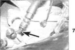
1If the caliper is just being displaced, the brake pads can be left in place and it is not necessary to disconnect the brake hose before removing the rear wheel. 2 If the caliper is being overhauled, read through the entire procedure first and make sure that you have obtained all the new parts required, including some new DOT 4 brake fluid. 3 Remove the brake pads (see Section 6). Note the alignment of the brake hose on the caliper, then unscrew the hose banjo bolt and separate the hose from the caliper (see illustration). Note:If you are planning to overhaul the caliper and don't have a source of compressed air to blow out the piston, the hydraulic system can be used to force the piston out of the body once the pads have been removed. Disconnect the hose once the piston has been sufficiently displaced. 4 Clamp the hose or wrap a plastic bag tightly around it to prevent fluid spills and stop dirt entering the system. Discard the sealing washers as new ones must be used on installation. 5 Remove the rear wheel (see Section 16). 6 If thecaliper is just being displaced. unscrew the bolt securing the rear brake hose clamp to the swingarm and secure the caliper and caliper bracket to the frame with a cable tie to avoid placing a strain on the hose 7»10 Brakes, wheels and tyres
Date: 2016-01-14; view: 573
|