CATEGORIES:
BiologyChemistryConstructionCultureEcologyEconomyElectronicsFinanceGeographyHistoryInformaticsLawMathematicsMechanicsMedicineOtherPedagogyPhilosophyPhysicsPolicyPsychologySociologySportTourism
B ... then pull the shock off the upper bracketInstallation 9Installation is the reverse of removal, noting the following. a) Apply molybdenum disulphide or copper-based grease to the spring pre-load adjusters. b) Ensure the spring pre-load adjusters are adjusted equally (see Section 11). c) Tighten the mounting bolts to the torque settings specified at the beginning of this Chapter. 11Suspension - adjustments Front forks 1The front forks are not adjustable. If the Rear shock absorbers
2 The rear shock absorbers are adjustable for
11.2 Align notches (A) with adjustment stopper (B). Turn spring seat anticlockwise (C) to increase pre-load, clockwise (D) to reduce pre-load 3To increase the pre-load, turn the spring seat anti-clockwise; to decrease the pre-load, turn the spring seat clockwise (see illustration 11.2). Note:Always ensure both shock absorber spring pre-load adjusters are adjusted equally. 12 Swingarm and drive chain slider - removal and ^ installation ^ Removal
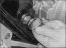
1 Place the bike on its centre stand. Remove the silencer (see Chapter 4) and the rear wheel (see Chapter 7). 2 Remove the chain tensioner assembly from each end of the swingarm (see illustration). 3On Rand T models, detach the brake pedal return spring from the lug on the swingarm (see illustration 3.9).Although not essential for swingarm removal, remove the split pin and unscrew the nut and bolt that secure the brake torque arm to the swingarm, noting the position of the plain and spring washers (seeillustration). Discard the split pin. 4 On V, W, SW, X, SX, Y and SY models, unscrew the bolt securing the rear brake hose clamp to the swingarm and secure the brake caliper bracket to the frame with a cable tie to avoid placing a strain on the hose (remove the right-hand side frame side panel if necessary). 5 Unscrew the nuts securing the chainguard to the swingarm and remove the shouldered 6*14 Frame, suspension and final drive
Date: 2016-01-14; view: 557
|