CATEGORIES:
BiologyChemistryConstructionCultureEcologyEconomyElectronicsFinanceGeographyHistoryInformaticsLawMathematicsMechanicsMedicineOtherPedagogyPhilosophyPhysicsPolicyPsychologySociologySportTourism
Slacken the top yoke clamp bolt (A). Fork top bolt (B)5.10b Ensure lever clamps with UP facingup
Unscrew the nut (A) and the pivot bolt (B) the handlebar (see illustration). d) Make sure the pin in the lower half ofeach switch housing locates in the hole in the handlebar. e) If removed, apply a suitable non-permanent locking compound to the handlebar end-weight retaining screws. If new grips are being fitted, secure them using a suitable adhesive to the handlebar (left-handgrip) or to the throttle twistgrip (right-hand grip). f) Tighten all bolts to the torque settings specified at the beginning of this Chapter. Handlebar levers Removal - clutch lever
11Slacken the clutch cable adjuster lockring 5.11a Slacken the lockring (A) and thread In the adjuster (B)... and thread the adjuster fully into the bracket to provide maximum freeplay in the cable (see illustration).Unscrew the lever pivot bolt locknut, then withdraw the pivot bolt and remove the lever, detaching the cable nipple as you do so (see illustration). Removal - brake lever 12Unscrew the lever pivot bolt locknut, then Installation 13Installation is the reverse of removal.
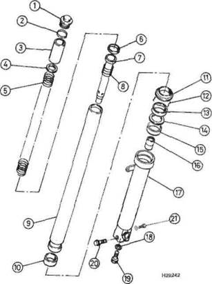
Removal Caution: Although not strictly necessary, before removing the forks it is recommended that the fairing (SW, SX and SY models) and radiator side panels (R, T, V, W, X and Y models) are removed (see Chapter 8). This will prevent accidental damage to the paintwork. 1 Remove the front wheel (see Chapter 7) and the front mudguard (see Chapter 8). 2 Remove each fork leg individually. 3 Unscrew the bolts securing the front brake caliper bracket to the right-hand fork slider and remove the caliper. Secure the caliper to the bike with a cable tie to ensure no strain is placed on the hydraulic hose. Discard the caliper bracket bolts as new ones must be fitted on reassembly (see Chapter 7). 4 Slacken but do not remove the fork clamp bolt in the top yoke (see Illustration).If the fork legs are going to be disassembled or the fork oil is going to be changed, slacken the fork top bolt while the leg is still clamped in the bottom yoke. 5 Slacken but do not remove the fork clamp bolt in the bottom yoke and remove the fork leg by twisting it and pulling it downwards (see illustration). Frame, suspension and final drive 6»7
Date: 2016-01-14; view: 679
|