CATEGORIES:
BiologyChemistryConstructionCultureEcologyEconomyElectronicsFinanceGeographyHistoryInformaticsLawMathematicsMechanicsMedicineOtherPedagogyPhilosophyPhysicsPolicyPsychologySociologySportTourism
Brake pedal - V, W, SW, X, SX, Y and SY modelsRemoval
15Remove the right-hand frame side panel (see Chapter 8). 16 Trace the wiring from the brake light switch and disconnect it at the black 2-pin connector. 17 Remove the silencer mounting nut and bolt (see Chapter 4, Section 13). 18 Ensure the rear brake fluid reservoir cap is secure and unscrew the bolt securing the
A Remove circlip (A) and washer (B)... B ... and remove pedal from bracket Lubricate pedal pivot before reassembly 6*4 Frame, suspension and final drive
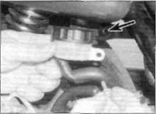
Remove the brake fluid reservoir from the frame bracket (arrowed) Pedal return spring (A) and brake light switch spring (B) Split pin (A), clevis pin (B), master Cylinder pushrod (C). Circlip (D) and Washer (E) retain pedal
reservoir to the frame (see illustration).Wrap rag around the reservoir to prevent accidental spillage and rest the reservoir in an upright position against the bike. 19 Unscrew the footrest bracket bolts and lift the bracket away from the bike, taking care not to strain the brake hose (see illustration 3.10). 20Disconnect the pedal return spring and the brake light switch spring from the lugs on the pedal (see illustration). 21Remove the split pin from the clevis pin securing the brake pedal to the brake master cylinder pushrod. Remove the clevis pin and separate the rod from the pedal (see illustration). 22The pedal pivots on the footrest bracket. Remove the circlip and washer from the pedal pivot and remove the pedal (see illustration 3.21). Installation 23Installation is the reverse of removal,
a) Apply molybdenum disulphide or copper-based grease to the brake pedal pivot (see illustration 3.14). b) Ensure the circlip is a firm fit in its groove on the brake pedal pivot. Don't forget the washer. c) Use a new split pin on the clevis pin securing the brake pedal to the master cylinder pushrod and bend the split pin ends securely. d) Tighten all bolts to the torque settings specified at the beginning of this Chapter. e) Check the operation of the rear brake and the brake light switch (see Chapter 1). Gearchange lever Removal 24 Note the alignment punch mark on the Installation 25 Installation is the reverse of removal. Align the lever slot with the punchmark in the end of the shaft. 26 Ensure that the pinch bolt is tightened securely. 4Stands - lb removal and installation |g Sidestand
1The sidestand is attached to a bracket on the left-hand side of the frame. Two springs, one inside the other, ensure that the stand is held In the retracted or extended position. 2 Support the bike on its centre stand and unhook the stand springs from the frame. 3 Unscrew the sidestand switch retaining bolt and remove the sidestand switch, noting how it fits (see illustration). 4Unscrew the nut securing the stand on the pivot bolt then unscrew the pivot bolt from the inside of the bracket and remove the stand. 5 On installation apply grease to the pivot bolt shank and tighten the nut securely. 6 Locate the tab on the inside of the sidestand switch in the hole in the stand and align the switch body with the stand spring post. Reconnect the sidestand springs and check that they hold the stand up securely when not in use - an accident is almost certain to occur if the stand extends while the machine is in motion. 7 Check the operation of the sidestand switch (see Chapter 1, Section 17). Centre stand 8 Support the bike in its sidestand. Unhook the two centre stand return springs from the frame. 9 Remove the split pin from the right-hand end of the stand pivot tube and withdraw the pivot tube from the left side to free the stand.
10 Clean all old grease and road dirt from the pivot tube and mounting lugs. Apply fresh grease to the pivot points and install the tube from the left side, passing it through the stand and the right side of the frame. Use a new split pin to secure the tube and bend its ends securely. 11Reconnect the springs, making sure that the spring sleeve is in place. Check that the stand is held securely retracted by its springs. 5 Handlebars and levers - removal and installation ;&, Handlebars Removal 1 Lift the cover, where fitted, on the rear view mirror mounting lock nuts, slacken the locknuts and unscrew the mirrors from the handlebar brackets. 2 Ensure the brake fluid reservoir cap is secure. Wrap rag around the reservoir to prevent accidental spillage. Unscrew the Frame, suspension and final drive 6*5
master cylinder clamp bolts and remove the clamp (see illustration).Position the master cylinder assembly clear of the handlebar, making sure no strain is placed on the hydraulic hose and the brake light switch wiring. Keep the master cylinder reservoir upright to prevent possible fluid leakage. 3 Unscrew the two screws from thecombined throttle twistgrip/handlebar switch and free the two halves of the switch unit from the handlebar (see illustration).Note the punchmark reference on the handlebar for reassembly. Detach the throttle cables from the throttle pulley - if necessary, slacken the throttle cable adjuster (see Chapter 1, Section 14). Position the switch unit away from the handlebar. 4 Unscrew the two clutch lever clamp bolts and remove the clamp (see illustration).Position the lever clear of the handlebar. making sure the cable and the clutch switch wiring is not unduly bent or strained. 5 Unscrew the two screws from thecombined choke/handlebar switch screws and free the two halves of the switch unit from the handlebar (see illustration 5.4).Note the punchmark reference on the handlebar for reassembly. Detach the choke cable from the lever and position the switch housing away from the handlebar. Date: 2016-01-14; view: 593
|


 5.2 Master cylinder clamp bolts (arrowed)